
Table of Contents
My first lathe backplate
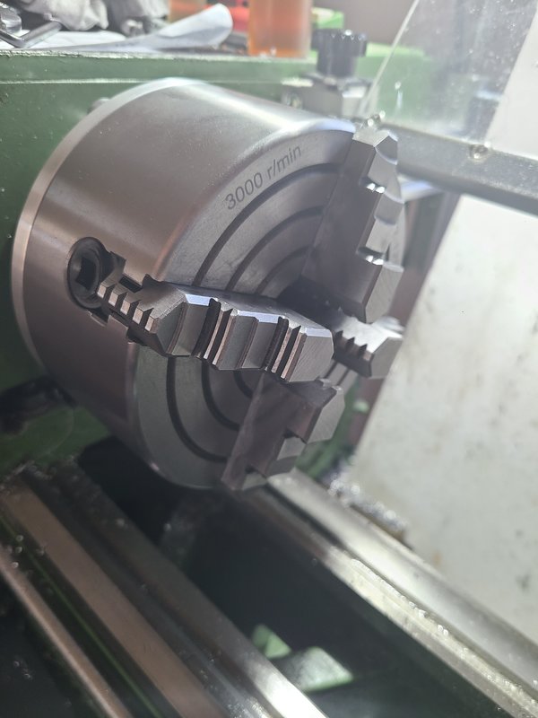
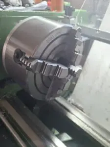
An independent four-jaw chuck had been on my list for quite some time.
Not because the existing chuck was fundamentally bad.
An independent four-jaw chuck can simply do things that quickly reach the limits of a conventional three-jaw chuck:
- hold square stock
- hold irregularly shaped workpieces
- set a workpiece deliberately off-center
- dial round stock in for the lowest practical runout
- and hold larger diameters between reversed jaws
The new chuck had a diameter of 125 mm.
Naturally, it did not fit the lathe directly.
The spindle nose follows some kind of Emco factory standard. Naturally.
Based on my research at the time, the Emcomat 8.6 probably uses an Emco factory standard that is sometimes referred to as KK1 and described as being similar to DIN 55026.
The dimensions I found were not consistent, however:
One source listed 40 to 41.77 mm, a width of 7.1 mm, and an angle of 7.125 degrees.
Another drawing for the Compact 8 listed 41.4 −0.2 to 42 h5, a width of 7 +0.2 mm, and an angle of 7° 7′ 30″.
I therefore did not rely on those figures for the build. I took the critical dimensions directly from the existing Emco chuck and the actual spindle nose instead.
In any case:
I needed a chuck backplate.
An aluminum offcut instead of a purchased backplate
I used an aluminum disc made from AlMg4.5Mn.
The disc was:
- approximately 130 mm in diameter
- 12 mm thick overall
- and already available as an offcut
I had also ordered a steel backplate intended for a Myford.
It might have been possible to adapt it as a source of material.
Before ruining the purchased steel backplate, I preferred to try the idea with the aluminum piece I already had.
There was always the possibility that the first version would not work.
Or, as temporary solutions occasionally do:
It will probably outlive me.
Taking the dimensions from the spindle nose and Emco chuck
I took the spindle-side dimensions from the existing Emco chuck and the spindle nose.
These included, in particular:
- the positions of the spindle-side fasteners
- the geometry around the spindle nose
- and the approximate positions of the required holes
I first transferred the dimensions and hole positions directly onto the aluminum disc at the workbench.
This was not a fully developed CAD design.
The existing machine and its correctly fitting original chuck were the drawing.
Aluminum disc with the holes and bolt circles marked by hand

The spindle-side dimensions were taken from the existing Emco chuck and initially marked directly on the disc.
An M12 thread as the first workholding aid
I cut an M12 thread into the approximate center of the disc using the drill stand.
I then screwed the plate onto an M12 threaded rod and used that to hold it on the lathe.
This mounting method was only a machining aid.
It allowed me to turn the disc on the Emcomat even though the final spindle-nose fitting did not yet exist.
In this setup, I:
- scribed the bolt circles for the spindle side
- marked the bolt circle for the new four-jaw chuck
- and bored the spindle-nose recess
The central M12 thread was therefore not part of the final mounting arrangement.
It was simply the means by which the backplate could be machined in the first place.
The spindle-nose fitting
The recess on the spindle side had to be machined so that the backplate would sit correctly on the existing spindle nose.
This area determines the basic position of the backplate relative to the spindle.
Simply holding it with three screws or studs would not have been sufficient.
The spindle nose provides the location.
The fasteners then pull the backplate against its intended seating face.

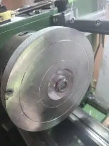
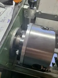
Disc mounted on the M12 threaded rod while machining the spindle-nose fitting
The temporary M12 thread made it possible to hold the disc on the lathe and machine the spindle-nose fitting.
Studs on the spindle side
After the first machining operation on the lathe, the disc returned to the drill stand.
That was where I produced the M8 threads for the spindle-side studs.
The studs were secured with Loctite 243.
I installed them with slight preload.
The idea was to avoid making the threadlocker work directly in the later load direction.
The studs were intended to seat mechanically, rather than being held in the tightening direction solely by the threadlocking compound.
Like the original chuck, the backplate is secured with nuts from the rear of the spindle mounting.
Aligning it on the spindle
After installing the studs, I mounted and checked the backplate on the Emcomat.
I adjusted the face to no more than approximately:
- 0.02 mm of face runout
From this stage onward, the backplate fitted the spindle nose as intended.
To make sure it could be refitted in the same orientation after removal, I marked its installed position with letter stamps and punch marks.
The backplate therefore has a defined position relative to the spindle.
There is no need to try every possible position after each removal to find the one that was originally set up.
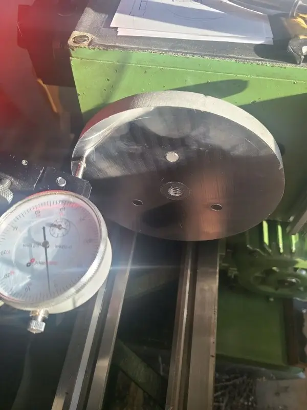
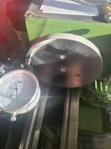
Backplate on the spindle nose with a dial indicator checking face runout
The backplate was mounted on the spindle and adjusted to no more than approximately 0.02 mm of face runout.
The central bore
Once the backplate sat correctly on the machine, the original M12 mounting thread could be removed.
I bored the center out to approximately 21 mm.
The spindle bore of the Emcomat is approximately 20 mm.
The slightly larger hole in the backplate kept the existing spindle bore clear without weakening the aluminum more than necessary.
The locating register for the four-jaw chuck
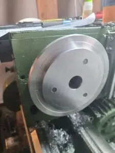
On the chuck side, the backplate received a matching locating register.
I machined it directly on the Emcomat while the backplate was already mounted in its final position.
This produced the chuck mounting surface with a direct reference to the actual spindle axis.
I adjusted the register until the four-jaw chuck sat on it with:
a close sliding fit with no perceptible play
The chuck could be fitted without visibly rocking on the register.
At the same time, it still had to remain possible to install and remove it.
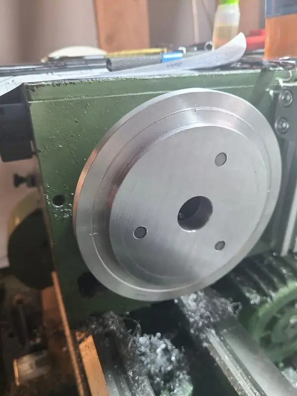
Finished locating register on the chuck side
The locating register for the four-jaw chuck was fitted while the backplate was mounted on the Emcomat.
Four holes for the new chuck
The four-jaw chuck is connected to the backplate with four screws.
I scribed the corresponding bolt circle on the lathe once again.
A quickly printed indexing disc from the 3D printer helped with the spacing.
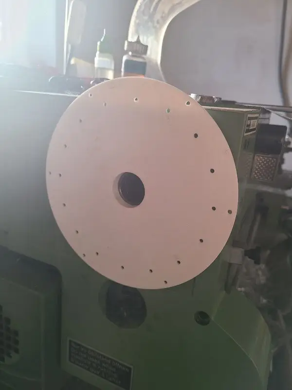
The final holes were then drilled using the drill stand.
The backplate has clearance holes on the chuck side.
The screws pass through the backplate and connect it to the chuck.
The backplate remains permanently attached to the four-jaw chuck.
When changing chucks, the chuck and backplate are therefore not separated from each other.
The complete assembly is removed from the spindle in the same way as the original chuck.
A chuck with its own dedicated backplate
The backplate belongs exclusively to this four-jaw chuck.
That is intentional.
A universal adapter plate would have required additional joints, more overhang, or further adjustment options.
Here, the chuck and backplate were intended to form one fixed assembly.
Changing the chuck on the machine therefore works as usual:
- Loosen the nuts at the rear.
- Remove the existing chuck.
- Fit the four-jaw chuck together with its backplate.
- Mount it in the marked orientation.
- Tighten the nuts again.
The connection between the chuck and backplate remains untouched.

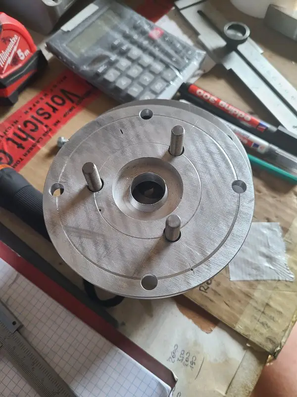

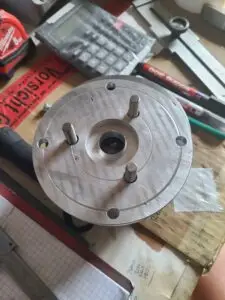
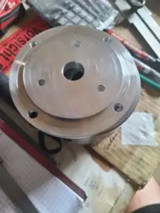
Spindle side with the three studs and chuck side with the four clearance holes
Three studs are fitted on the spindle side. The four-jaw chuck is permanently connected to the backplate through four clearance holes.
Why an independent four-jaw chuck?
On an independent four-jaw chuck, each jaw is adjusted separately.
This takes longer than clamping a workpiece in a self-centering three-jaw chuck.
In return, workpieces can be positioned very deliberately.
Possible applications include:
- round stock dialed in to a chosen runout
- square stock
- rectangular workpieces
- irregular castings
- previously machined surfaces
- deliberately eccentric setups
- and workpieces that cannot sensibly be held in a three-jaw chuck
Depending on the workpiece, alignment is carried out using a dial indicator, scribed lines, or existing surfaces.
Each jaw affects the opposite side.
It takes a while.
In return, the final position is not dictated by the inherent runout of a self-centering chuck.
A larger gripping range and reversible jaws
Compared with my previous setup, the new chuck also provides:
- a larger gripping diameter
- reversible jaws
- and more room for awkwardly shaped workpieces
The reversible jaws in particular increase the usable diameter considerably.
The benefit is therefore not limited to independent adjustment.
The size of the chuck itself opens up additional possibilities.
The thin aluminum disc
The material thickness led to justified concerns in the forum.
The disc is only 12 mm thick overall.
In parts of the outer rim, the machined register leaves only approximately 7 mm of material.
That is not generous.
The factors that need to be considered there include:
- the weight of the chuck
- the clamped workpiece
- the cutting forces
- and possible elastic deformation
I therefore selected the mounting screws and washers so that, on the rear side, they partly extended into or bore against the thicker section of the disc.
The load is therefore not introduced exclusively into the thinnest part of the outer rim.
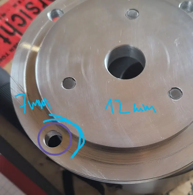
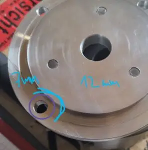
Close-up of the backplate with the 7 mm and 12 mm material thicknesses marked
The backplate is 12 mm thick overall. In parts of the outer rim, only approximately 7 mm of material remains.
Will it hold, or will it flex?
I was reasonably confident that the backplate would not simply break.
That was not the only question, however.
Stiffness matters in a chuck mounting as well.
Elastic deformation could become noticeable as:
- vibration
- changed face runout under load
- poorer surface finish
- or a generally undesirable flexible connection between the chuck and spindle
The forum discussion included different assessments.
Some considered 12 mm of aluminum sufficient for the small Emcomat.
Others pointed out that the outer rim, only approximately 7 mm thick, might be unnecessarily flexible.
Both arguments are understandable.
The backplate was deliberately made as a first attempt from material I already had.
The original thread does not document a measured deformation or a reliable comparison with a thicker steel backplate.
Aluminum or steel?
A steel backplate would be stiffer with the same geometry.
It would also be heavier and somewhat more involved to machine on the small lathe.
The aluminum disc offered several advantages for the first attempt:
- The material was already available.
- It was easier to machine on the small lathe.
- Mistakes would have been less annoying.
- The purchased steel backplate remained available as a reserve.
- The basic idea could first be tested in practice.
A thicker aluminum or steel backplate would be an option for a later final version.
Whether that is necessary depends on the behavior in actual use.
What worked well during the build
Considering the equipment I had available, the basic machining sequence was surprisingly straightforward:
- Take the dimensions from the original chuck.
- Produce the temporary M12 thread.
- Mount the disc using the threaded rod.
- Machine the spindle-nose fitting.
- Install the studs.
- Align the backplate on the machine.
- Mark the installed orientation.
- Bore out the central hole.
- Machine the chuck register while mounted.
- Mark the bolt circle and drill the holes.
- Permanently mount the four-jaw chuck.
The important part was machining the critical locating surfaces on the machine itself.
That gave them a direct reference to the existing spindle axis.
What I would do differently today
Use thicker material
If I built another one, I would probably choose a thicker disc.
Not necessarily because the documented version had obviously failed.
A thicker backplate would, however, settle the concerns about the outer rim being only approximately 7 mm thick before they even started.
Lay out the bolt circles more systematically
The bolt circles were scribed and divided using a printed indexing disc.
It worked.
A properly laid-out hole pattern, a template, or a real indexing fixture would make the positions easier to transfer unambiguously.
Consider the steel backplate as the final solution
The Myford steel backplate remained unused as a possible source of material.
If the aluminum version proved too flexible in use, it would be a candidate for a second version.
Its diameter and thickness would first need to be checked against the Emcomat and the chuck.
Document loads and runout
The face runout of the unloaded backplate was checked during the build.
Additional useful measurements would include:
- face runout with the chuck installed
- the radial runout of a clamped test bar
- behavior with different workpiece weights
- and a comparison before and after heavier machining
These values were not documented in the original thread.
Current documented status
By the end of the original thread, the four-jaw chuck was fully assembled and ready for use.
The following points were confirmed:
- The backplate fits the spindle nose.
- The spindle-side face was adjusted to no more than approximately 0.02 mm of face runout.
- The installed orientation was marked.
- The spindle bore remains open through an approximately 21 mm central hole.
- The locating register fits the new chuck without perceptible play.
- The chuck is permanently connected to the backplate.
- The complete assembly can be mounted on the Emcomat in the same way as the original chuck.
The following points are not documented over the long term:
- stiffness under high loads
- possible elastic deformation of the thin outer rim
- and its condition after extended use
These therefore remain points to observe in use, not results that have already been confirmed.
Retrospective
The chuck backplate was made from an aluminum disc I already had, a drill stand, and the Emcomat itself.
First, an M12 thread was needed simply to hold the actual component on the machine at all.
The Emcomat then gradually machined the surfaces through which the new chuck would later be connected to its own spindle.
The final result included:
- three spindle-side studs
- four chuck-side mounting holes
- a fitted spindle-nose recess
- a locating register with no perceptible play
- and a 125 mm independent four-jaw chuck
The backplate is thinner than I would make it today if I had complete freedom of material choice.
It was made from what I had available, however, and fulfilled its purpose in the documented condition.
An offcut became the connection to a tool that considerably expands what the Emcomat can hold.
Picture gallery


Forum discussion (German)
The original build and the discussion about material thickness, bolt circles, and the aluminum construction are documented in the forum:
Forum discussion: Backplate for a 125 mm four-jaw chuck
This article describes my specific backplate and the documented machining process. A lathe chuck is a heavy rotating machine component. Material, fasteners, fits, balance, permissible speed, and condition must be assessed independently for the particular setup. If there is any doubt, the backplate must not be used.
How would you build the backplate?
The 12 mm aluminum disc worked in the documented setup. The outer rim, only approximately 7 mm thick in places, nevertheless remains the obvious point for discussion.
Have you built a chuck backplate from aluminum, deliberately chosen steel, or measured its stiffness under load?
I am particularly interested in practical experience with thin backplates on small lathes. Alternative approaches, long-term experience, and well-reasoned criticism are very welcome in the comments.
Leave a Reply