
Table of Contents
Know the feeling?
You briefly reach for a component.
It wobbles.
You think:
That can be better!
And just like that, the odyssey begins.
My father owned an older Tormek 1200. He never really warmed to the machine. For knives and similar jobs, he later bought a Ken Onion Work Sharp and was much happier with it.
The Tormek was therefore going to be sold, or at least stop standing around.
Long story short:
A Tormekian wet grinder moved in.
One wiggle of the support bar
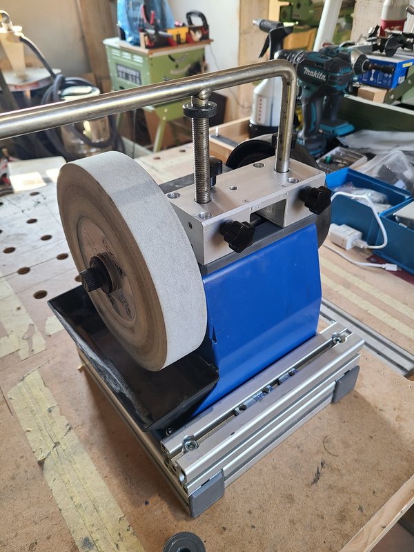
I placed the machine on the workbench and slid the Universal Support into its “guides.”
Then I gently moved the free end of the bar back and forth.
The entire construction gave way in every direction.
This older version has a plastic housing. Molded into it are guide mounts that are essentially held and clamped by retaining rings.
It works in principle.
On my machine, it did not feel particularly rigid.
The farther out I held the bar, the more obvious the flexibility became.
It was not just the bar moving inside the bores.
The entire area of the housing around the guides twisted along with it.
The wobble toy had to go.
What the guide needs to do
The Universal Support carries the various sharpening jigs.
Its position determines, among other things:
- the distance from the grinding wheel
- the height of the jig
- the grinding angle
- and the guidance of the workpiece, such as a knife
A small amount of play at the mounting point becomes much more noticeable at the long, unsupported end of the bar.
That does not automatically mean the original machine is incapable of sharpening a knife.
What bothered me was that the guide visibly gave way under light hand pressure. It was repeatable, perhaps. But it was not precise.
I wanted:
- a larger supporting base
- two properly guided bearing points
- a rigid clamping system
- and a support bar that would still slide easily
A new aluminum bridge
The new guide was no longer going to rely entirely on the plastic housing for support.
For this, I made a solid aluminum block – or rather, an aluminum bridge – connecting both guide positions.
New igus plain bushings would be fitted into this block.
The basic idea was simple:
Instead of improving two separate wobbly points, combine both guides into a single rigid component.
The aluminum block therefore performs several tasks:
- holding the two plain bushings
- connecting the two guide points
- holding the clamping screws
- supporting itself on a new base plate
- and distributing the forces over a larger area of the plastic housing
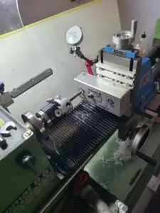
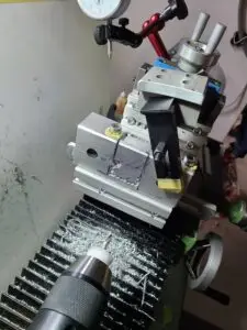
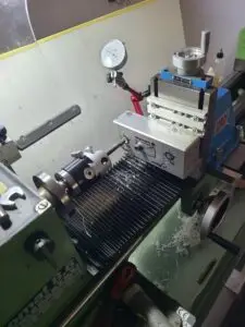
Boring the bushing holes on the Emcomat
The new igus bushings required two mounting bores that were aligned as accurately as possible.
I therefore mounted the aluminum block on the Emcomat.
Once again, the main challenge was not simply drilling the holes.
The long block had to be held and aligned so that both bushings would later guide the same Universal Support without binding against each other.
The bores were finished on the lathe.
This allowed me to bring their diameters under control and match them to the bushings being used.
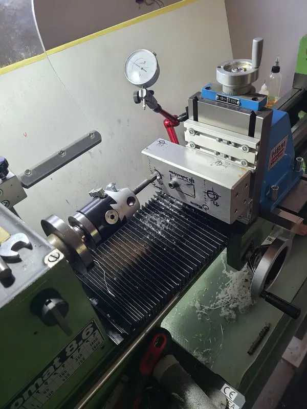
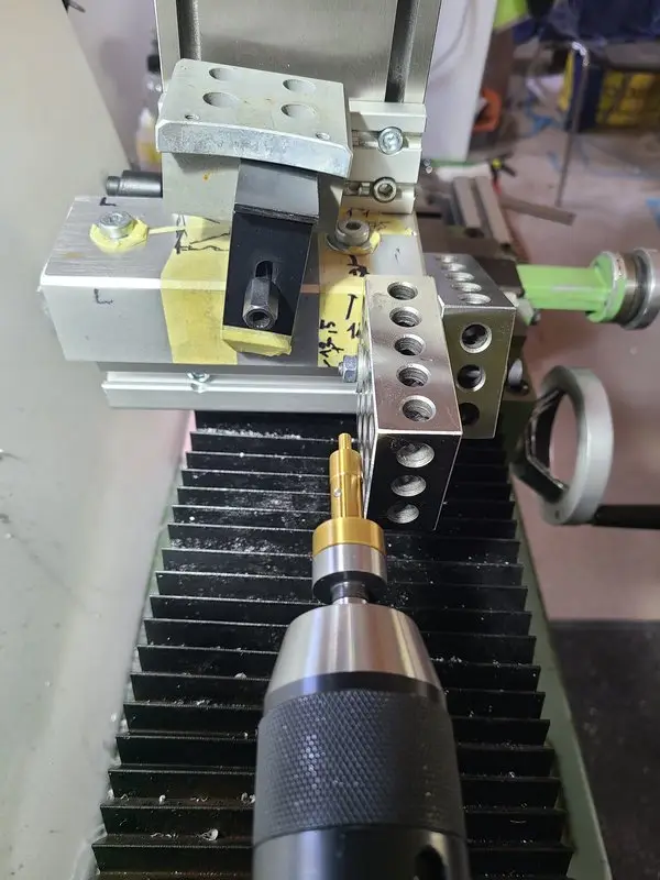
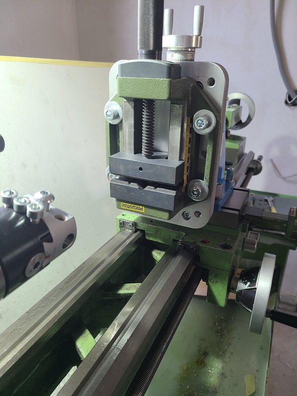
The bores for the igus plain bushings were made on the Emcomat. Both guide positions needed to align with each other as cleanly as possible.
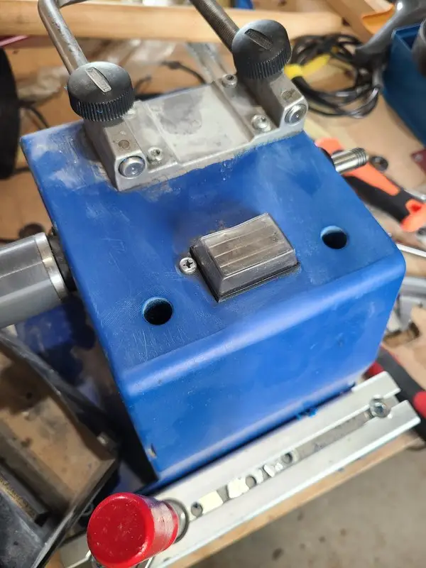
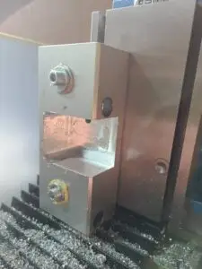
The switch was in the way
A sufficiently large aluminum block could simply have been placed across the top of the machine.
Unfortunately, that was where the power switch was located.
The new guide could not cover the switch or prevent it from being operated.
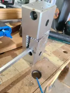
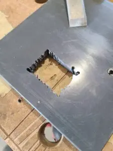
The aluminum block therefore needed a suitable cutout.
A larger pocket was worked into the block so that the switch would remain accessible.
I did not have a milling machine.
Once again, the work was done with whatever was available:
- drilling holes
- removing the material step by step
- working out the contour
- and doing a little fitting and filing by hand
The pocket was not made this large because it was an especially elegant shape.
It was made large enough to leave room for both the switch and my fingers.
Off with its head
The first aluminum blank was still a closed, solid block.
To turn it into the bridge I needed, a large section had to be removed from the middle.
At some point, the decision became fairly obvious:
Off with its head.
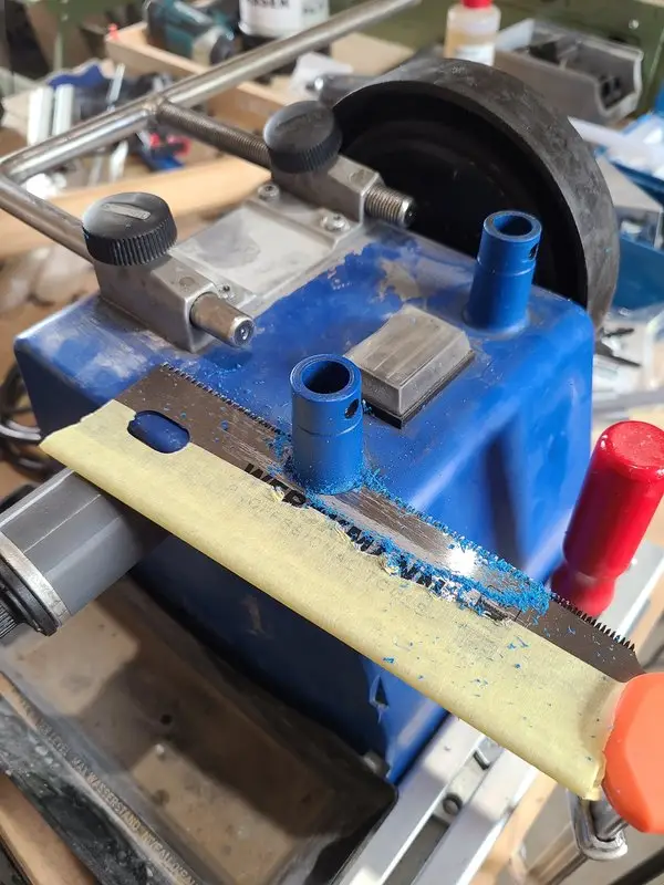
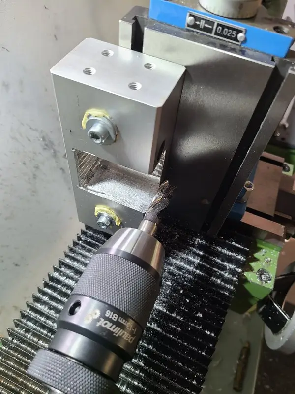
I then worked the large switch cutout into the aluminum block.
The machining marks remained visible.
The component did not need to look like an industrial casting.
It needed to:
- sit properly on its base
- keep the bushings aligned
- provide sufficient clearance
- and be considerably more rigid than the original construction



A new plastic base plate
The new aluminum guide needed a solid supporting surface.
The original plastic housing had not been designed for this.
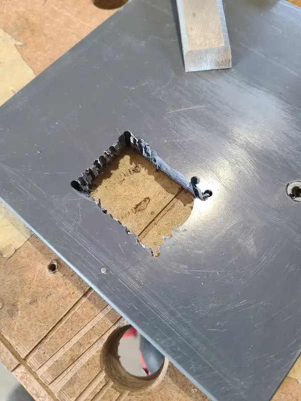
The contour was marked, drilled, cut out, and gradually adjusted.
The new construction was intended to sit across a separate base plate as fully as possible, rather than resting on a few isolated points of the old plastic housing.
An additional plastic plate was fitted to the existing housing.
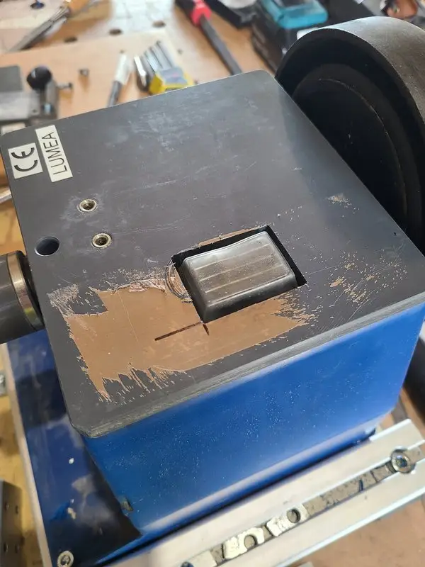
This plate forms the new upper base of the construction.
It was bonded across its entire surface with Sikaflex 554.
The adhesive joint was intended to:
- distribute the forces over a larger area
- compensate for uneven surfaces
- hold the plate securely on the housing
- and still leave open the possibility of removing it again later
I did not want to destroy the old machine more permanently than necessary.
The construction was substantially modified, but it should still remain removable in principle if I ever come up with a different solution.
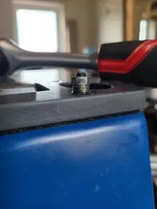
Ensat threaded inserts instead of screws in plastic
The aluminum block needed to be connected reliably to the new base plate.
I did not want to use simple threads cut directly into the plastic.
Instead, I installed Ensat threaded inserts.
The threads for the clamping screws were fitted with inserts as well.
This prevents the screws from bearing directly on the comparatively soft plate material.
The inserts provide:
- more durable threads
- more controlled tightening
- less wear
- and a repairable connection
The clamping screws in particular are loosened and tightened regularly.
A thread cut directly into the plastic would not have inspired much confidence in the long term.

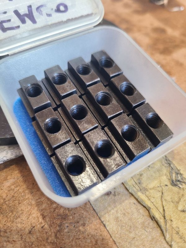
Simple DIY tool for installing Ensat inserts, made from set screws and a nut.

The new bushing guide
The two igus plain bushings were fitted into the aluminum block.
The Universal Support no longer runs directly inside the old guide mounts molded into the housing.
Instead, it is guided by two bushings installed in one common solid component.
The difference is not simply the material of the bushings.
The important part is the connection between them.
The two bearing positions can no longer twist independently along with the plastic housing.
They are now part of the same rigid bridge.
Clamping without binding the guide
In addition to the plain bushings, each side needed its own clamp.
With the clamps released, the Universal Support should slide easily.
Once adjusted, it needs to remain securely in position.
The clamping screws also sit in Ensat inserts.
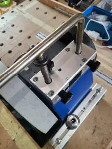
For the documented version, I initially used star knobs.
They are easy to operate, but relatively wide.
As a possible later modification, I considered making narrower knurled knobs.
That would mainly be a matter of:
- space
- ease of use
- and a slightly less expansive appearance
Functionally, the existing star knobs already worked.
A lot of holes for an apparently simple part
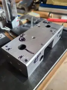
Once the major machining operations were complete, there was still quite a bit of drilling left to do.
Holes were needed for, among other things:
- mounting the aluminum block
- the threaded inserts
- the two plain bushings
- the clamping screws
- existing parts of the machine
- and the switch, which still needed to remain accessible
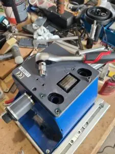
The unfinished block therefore carries plenty of markings in the photographs.
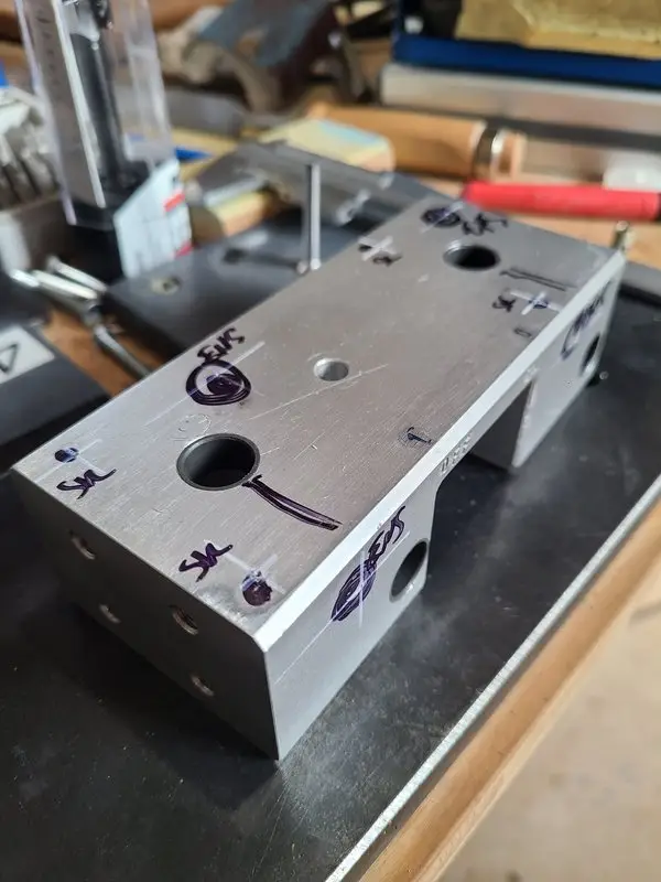
Not every line was part of an elegant construction drawing.
Some of them appeared directly during the build:
- another screw head here
- not enough clearance there
- the switch is located at this point
- and the clamping screw will eventually need to go over there
The construction developed on the actual housing, not on paper.
Mounting it on the Tormek 1200
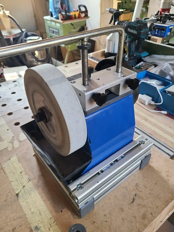
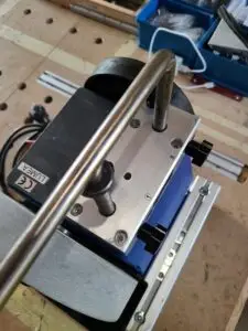
Once everything was finished, the base plate and aluminum bridge were mounted on the machine.
The assembly now consists of:
- the original housing
- the bonded-on plastic base plate
- the bolted aluminum block
- two igus plain bushings
- the clamping screws
- and the original Universal Support
The two vertical legs of the support run through the new bushings.
The height adjustment and existing Tormek jigs remain usable in principle.
The machine now looks considerably more technical than it did before.
That was not the actual goal.
With a large aluminum block sitting on a blue plastic housing, however, it was difficult to avoid.
Silky-smooth instead of wobbly
The result was exactly what I had wanted.
The Universal Support slides very easily inside the new bushings.
With the clamps released, it can be adjusted cleanly.
Once clamped, it sits considerably more rigidly than before.
In the original forum thread, I described the result like this:
Silky-smooth movement. Absolutely no comparison to the wobble toy it was before.
I was happy with that.
I did not perform a quantitative measurement of the rigidity.
What is documented is the practical observation:
- considerably less movement that can be felt by hand
- smooth sliding
- working clamps
- and a construction that inspires considerably more confidence
The existing support bar is still too short
The new guide did not solve another problem.
Depending on the knife or jig being used, the horizontal support bar is relatively short.
For some jobs, it does not extend far enough to the side.
For this reason, I ordered 12 mm H7-ground silver steel – or drill rod, in American terminology.
This was intended for a second, longer Universal Support.
The original support could then remain fitted for honing, for example, or be used for other setups.
A new support without bending or welding
For the planned longer support, I did not want to bend or weld the bar.
Instead, I planned a multi-part construction:
- two vertical bars
- each with a threaded stud
- one horizontal bar
- with blind holes and internal threads
The vertical parts would be screwed into the horizontal bar.
This would offer several advantages:
- no heat distortion from welding
- no potentially inaccurate bend
- geometry that can be set up accurately
- replaceable individual parts
- and sufficient clearance for the existing jigs
I have not finished this support yet. In fact, I have not even started building it.
What was deliberately left unchanged
The modification was not intended to reinvent the entire machine.
The following parts remained:
- the grinding wheel and drive
- the existing height adjustment
- the original Universal Support
- the existing Tormek jigs
- the power switch
- and the basic operating principle
The main change was the base in which the Universal Support is guided and clamped.
The machine therefore remains a Tormek 1200.
Only the wobbly part received considerably more aluminum than the manufacturer had originally intended.
What I would do differently today
Draw the construction more completely first
Many of the clearances and holes were determined directly during fabrication.
For a second version, I would first record the following more carefully:
- the position of the switch
- the existing housing contour
- access to the screws
- the distance between the bushings
- and the necessary tool clearances
That would have avoided many later – and quite a few on-the-fly – adjustments.
Build the longer support at the same time
The improved guide solved the wobbling.
The limited length of the original bar remained.
If I were doing the modification again, I would probably plan the new guide and the longer Universal Support as a single project.
Use narrower clamping knobs
The star knobs work well.
Narrower knurled knobs would project less to the sides and make the upper area look a little tidier.
Build a simpler fixture for the aluminum block
Machining the long block on the Emcomat was possible, but involved.
A better-prepared fixture – or, well, a milling machine – would have made producing the pockets and cutouts considerably easier.
The Emcomat was pressed into service as a milling machine once again.
It is used to that by now.
Current documented status
- an additional plastic base plate
- full-surface bonding with Sikaflex 554
- a solid aluminum block
- igus plain bushings
- Ensat threaded inserts
- separate clamping screws
- silky-smooth movement of the Universal Support
- and considerably less flexibility that can be felt by hand
Still open or planned:
- narrower knurled clamping knobs
- a second, longer Universal Support
- and its multi-part bolted construction made from 12 mm silver steel
Retrospective
It started with an old grinding machine that my father no longer wanted to use.
I placed it on the workbench.
Slid the Universal Support into place.
Wiggled it briefly.
What followed was:
- a large aluminum block
- two bored bushing seats
- a drilled and milled cutout for the switch
- a new plastic base plate
- a housing that had been cut open
- Ensat threaded inserts
- igus plain bushings
- new clamping screws and knobs
- and a plan for a longer Universal Support
All because the bar wobbled a little.
Entirely reasonable, I would say.
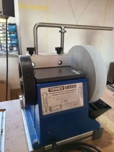
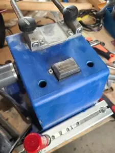
Image gallery










Forum discussion (German)
The original modification was documented with numerous photographs on the Zerspanungsbude forum:
Forum discussion: Tormek 1200 – Stabilizing the Universal Support
This article documents my specific modification. Any changes to the housing, electrical controls, or guide components must be carried out in a way that prevents damage to wiring, switches, or moving machine parts. The machine must be fully disconnected from the power supply before the housing is opened or modified.
How stable is the guide on your Tormek?
On my old Tormek 1200, the Universal Support itself was not the only part that moved. The original guides in the plastic housing also had considerably more play than I liked.
Have you noticed the same problem on your Tormek or similar grinders, or is the guide better supported on later versions?
I am particularly interested in long-term experience with different bushings, additional clamping arrangements, or similar modifications. Solutions that avoid a large aluminum bridge altogether are very welcome in the comments as well.
Leave a Reply