

Table of Contents
I Would Have Liked a Lathe
A milling machine too.
At the time, my collection of machines was rather… let’s say: modest.
On the wish list were:
- lathe
- milling machine
- drill press
What I actually had was:
- angle grinder
- files
- hand saw
- drill stand
- vise
- stick welder
- and the usual hand tools
So, not nothing.
But not necessarily what you would normally use when several round and reasonably similar clamping devices for a welding table are supposed to emerge.
What I wanted anyway were ball-lock clamping pins and simple drop-in stops for my fixture plate.
The shape of these parts practically calls for a lathe.
I did not have one. So it had to work another way.
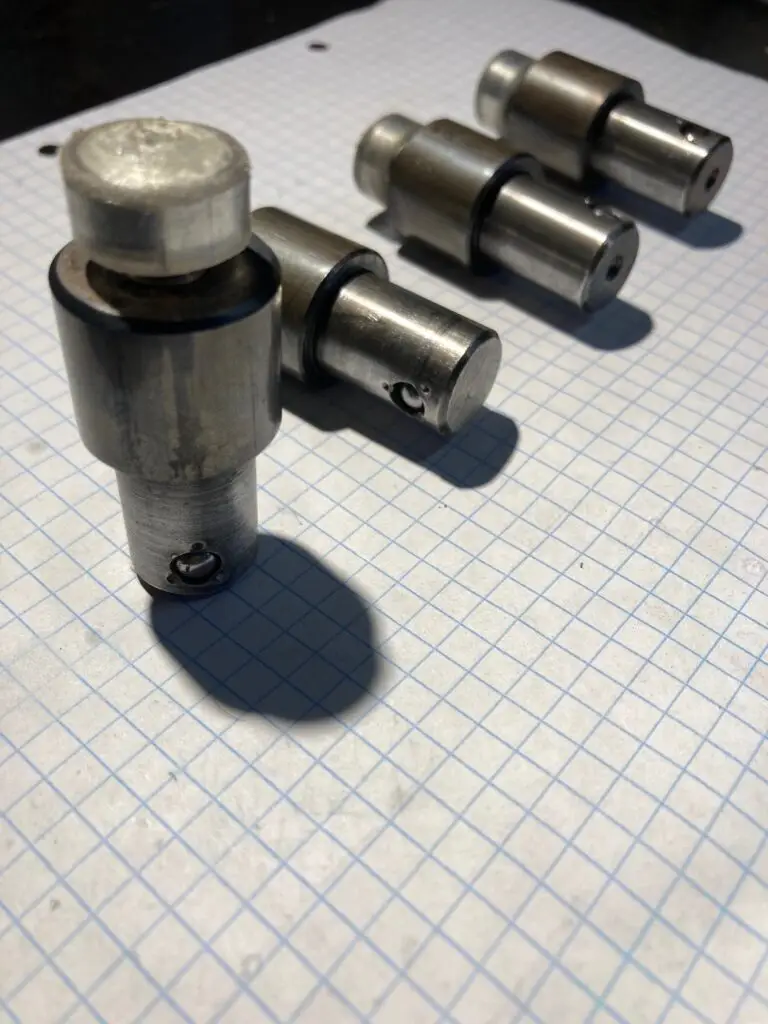
An Early Workshop Project
The ball-lock clamping pins were among the first projects I documented in more detail and shared in a forum.
My training as a mechanical engineering technician was already a long way behind me by then.
After several years working on production machines and assembling glass-grinding machines, I had moved professionally all the way into the ranks of the desk jockeys.
In my free time, though, I still liked having a file in my hand.
So the basic feel for metal was still there.
What was mainly missing were—and still are—machines.
That is exactly why this project fits WerkstattDenke. rather well today:
Do not wait until the perfect set of machines is available someday. Rather think about what can be done with the means already at hand.
What the Pins Needed to Clamp
My welding-table plate has:
- holes 16 millimeters in diameter
- eight millimeters of material thickness
The clamping parts I already had were mainly eight millimeters thick, with some at six millimeters.
The pins therefore had to cover two typical combinations at first:
- eight-millimeter fixture plate plus an eight-millimeter clamping part
- eight-millimeter fixture plate plus a six-millimeter clamping part
For smaller clamping thicknesses, I could add spacer rings.
A suitable section of the precision tube I already had could simply be used for that.
In addition to the actual clamping pins, I also wanted simple drop-in stops.
They do not need a clamping mechanism. They are simply inserted into the holes and serve as:
- stops
- reference points
- alignment aids
- or quick locating surfaces for a workpiece
I made ten of them.
Material from the Scrap Yard
The starting material was not a purchased clamping system.
I used:
- 16-millimeter round bar from the scrap yard
- 22 × 3 millimeter precision tube from the scrap yard
- six-millimeter balls from an old ball bearing
- M8 socket-head screws
- small M5 set screws
- PVC hose
- and a little hot glue
I simply got lucky with the precision tube.
Its inside diameter matched the 16-millimeter round bar exactly.
That allowed the tube and round bar to form a stepped shape together—something that otherwise would probably have been turned from a larger piece of solid stock.
I used the same basic principle for both the ball-lock clamping pins and the ten simple drop-in stops.
A Sketch Had to Be Enough
No proper technical drawing was made before I started.
I made a somewhat rough and rustic hand sketch on paper.

It showed:
- the operating principle
- the position of the balls
- the clamping screw
- the cone on the screw
- the intended clamping length
- and a few important dimensions
The sketch was only meant for me.
And, well, it looked like it. 🙂
It was still enough for the first attempt.
Especially for small projects, I prefer a quick, usable sketch to a beautiful plan that takes longer to produce than the part itself. At least that is how it works for me.
How the Ball-Lock Clamping Pin Works
Two opposing balls sit inside the pin.
An M8 screw is threaded in from above. Its lower end is ground into a cone.
As the screw is tightened, the cone pushes both balls outward.
The balls project slightly through the cross holes and bear against the underside of the fixture plate.
At the top, the collar of the pin—or the part being clamped—provides the opposing support.
This pulls the fixture plate and clamping part together.
The principle is simple.
The important points are:
- The balls must not fall out.
- They must move outward far enough.
- The pin must still fit through the 16-millimeter hole.
- The ball position must match the intended clamping thickness.
- And the screw must move both balls as evenly as possible.
A Pin from Tube and Round Bar
First I cut the tube and round bar to length.
The 16-millimeter round bar forms the actual body of the pin.
The precision tube forms the larger collar.
I did not have a press.
So the two parts were joined with a large sledgehammer and a wooden block.
Or, to put it more honestly:
They were simply hammered into one another.
The wooden block was meant to keep direct hammer blows from unnecessarily damaging the end face.
I then added two tack welds at the top. They keep the tube and round bar from moving against each other later.
Afterward, I ground the welds flush again and cleaned up the top surface.
That turned two pieces of scrap into a stepped pin.
Not turned on a lathe.
Not made in a particularly elegant way.
But round and sturdy enough for the intended job.
Ten Stops Built the Same Way
The simple drop-in stops were made in almost the same way.
Here too, round bar and tube were driven together, welded at the top, and cleaned up afterward.
They have neither balls nor a clamping screw.
They are basically just pins with a collar.
They are inserted into the fixture plate and can, for example:
- position workpieces
- align edges
- set distances using the hole pattern
- establish right angles
- or prepare a setup before clamping
Precisely because they are so simple, they can be used quickly and in many different ways.
The Critical Distance
For the clamping pins, the distance between the collar and the center of the cross holes is critical.
The center of the cross hole later corresponds to the center of the ball.
With a combination of:
- an eight-millimeter fixture plate
- and an eight-millimeter clamping part
the total clamping thickness is 16 millimeters.
I placed the center of the balls about one millimeter below the underside of that combination—roughly 17 millimeters from the collar.
This allows the balls to bear against the underside of the plate instead of simply passing by the material.
There was still enough material for the eight-plus-six-millimeter combination. If necessary, the clamping range could also be adjusted with spacers.
The pins were not meant to work with only one precisely matched material combination.
Repeatable Cross Holes Without a Milling Machine
The cross holes in all four clamping pins had to be approximately the same distance from the collar.
I did not have a proper drilling fixture.
So, on the drill stand, I used the side face of the vise jaw as a length stop.
The first pin was set to the correct distance.
The vise then stayed fixed in place.
I pushed each of the remaining pins against the same jaw face and drilled them in the same position.
This was not coordinate drilling.
For this purpose, however, the repeatability was sufficient.
The holes did not need to be identical to within a few hundredths of a millimeter.
The ball position and clamping range simply needed to be as similar as possible on all four pins.
A Plywood Plate as a Centering Aid
After the cross holes, the axial holes and threads were still missing.
Simply laying a round part in the vise and drilling it on center by eye seemed unnecessarily adventurous.
So I clamped a piece of plywood in the vise and drilled a hole in it with a 16-millimeter Forstner bit.
That hole then served as a holder for the pins.
They stood upright in it and were at least centered well enough.
From above, I could drill the hole for the M8 thread.
The pin was then turned over, and the M5 thread was made on the underside.
The wooden holder was not a conventional metalworking fixture.
But it did not need to withstand high forces either.
It only had to hold and guide the pin for a few drilling operations.
It worked surprisingly well for that.
The M5 Set Screw Keeps the Balls Apart
The M5 thread on the underside accepts a small set screw.
This screw does not carry any of the actual clamping force.
It merely prevents both balls from moving to the same side when the M8 screw is backed out too far.
Without this separation, the balls could shift into an unfavorable position inside the pin.
When the screw was tightened again, the cone might then catch only one ball or push one ball in the wrong direction.
The M5 set screw is therefore only a “ball separator.”
A small detail.
But one that prevents the mechanism from having to sort itself out again every time it is opened.
The Cone Was Ground with an Angle Grinder
The lower end of the M8 screw had to push both balls outward.
That required a conical tip.
A lathe would have been the obvious way to make it.
Instead, I clamped the angle grinder in the vise and ground the screws by hand.
The result was not a precision surface.
But the cone did not need to look pretty.
It needed to:
- reach both balls
- push them outward at roughly the same time
- avoid immediately jamming
- and provide enough travel
It still fulfills that job today.
The Balls Must Not Fall Out
The six-millimeter balls came from an old ball bearing.
They are inserted from above through the tap-drill hole for the M8 thread.
The side cross holes must not remain open far enough for the balls to fall out completely.
A bushing or some other additional retaining insert would have been possible.
I chose a simpler solution:
Using center-punch marks, I displaced the edges of the cross holes slightly inward.
This reduced the free opening just enough to keep the balls inside the pin.
They can still project far enough, but they cannot fall out completely.
Elegant is something else.
It works anyway.
More Clamping Force Than Expected
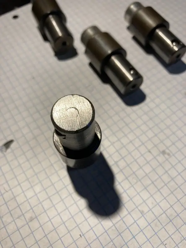
Originally, I wanted to add a proper handle or a nut to the M8 screws.
During the first test, however, hand tightening alone produced a surprisingly strong clamping action.
A normal hex key would have been more of a risk.
It would make it possible to apply far more force than the small balls and the fixture plate need for my use.
So I deliberately prevented the use of a tool.
The hex socket was filled with hot glue.
So that nobody—including me—would get the idea of putting a key in there.
I then slipped a short piece of PVC hose over the screw head.
The hose provides:
- enough grip
- hand operation
- and a simple limit on the force that can be transmitted
The PVC hose therefore serves as both a handle and a crude torque limiter.
“Crude” is not meant as an insult here.
Four Clamping Pins and Ten Stops
In the end, I made:
- four ball-lock clamping pins
- ten simple drop-in stops
Several improvised operations had to be repeatable enough:
- cutting to length
- driving the tube and round bar together
- adding tack welds
- cleaning the surfaces up again
- drilling the cross holes against a stop
- drilling the axial holes using the wooden holder
- cutting the threads
- grinding the cones on the screws
- inserting the balls
- reducing the ball openings with center-punch marks
- and installing the ball separator
The finished parts do not look like industrially manufactured clamping hardware.
That was not the goal either.
They simply needed to work with the means available.
They do.
The Objection from the Forum
A technically valid objection came up in the forum discussion:
The two balls load the lower edge of the fixture-plate hole only at two points. If tightened hard, this could cause pressure marks, burrs, or deformation. A clamping design with a larger contact area would distribute the force more evenly.
My assessment at the time was that minor marks would be acceptable for my occasional use. If a burr or raised edge actually developed, the affected hole could still be lightly deburred or countersunk.
There is now genuine long-term experience to compare with that assumption.
Light pressure marks are visible on some holes. So far, however, they have not caused a practical problem. The pins can still be inserted and removed, the holes remain usable, and the clamping function is not impaired.
You can see the load a little. It does not matter.
Tightening the screws only by hand limits the applied force. That is exactly why the hot glue is still in the hex socket.
Forum discussion (German): DIY ball-lock clamping pins for a welding table and fixture plate
Long-Term Experience
The four ball-lock clamping pins are still here and still functional.
They are only used occasionally, though. That has less to do with the pins than with my welding table, which still consists mainly of the fixture plate. The planned base is still missing, and between uses the plate is exceptionally reliable at collecting other stuff.
- The screws still turn.
- The balls move freely.
- The M5 set screws keep them separated.
- The clamping force is still strong.
The PVC hose is also still on the screw heads, and the hot glue still fills the hex sockets. I could make both of those things look better today.
So far, there has been no need.
Sometimes that is the best reason not to replace a working temporary fix with a prettier temporary fix.
The ten simple drop-in stops are still in use as well. They have no mechanism that could seize, and they can be inserted quickly wherever a reference edge is needed.
What I Would Do Differently Today
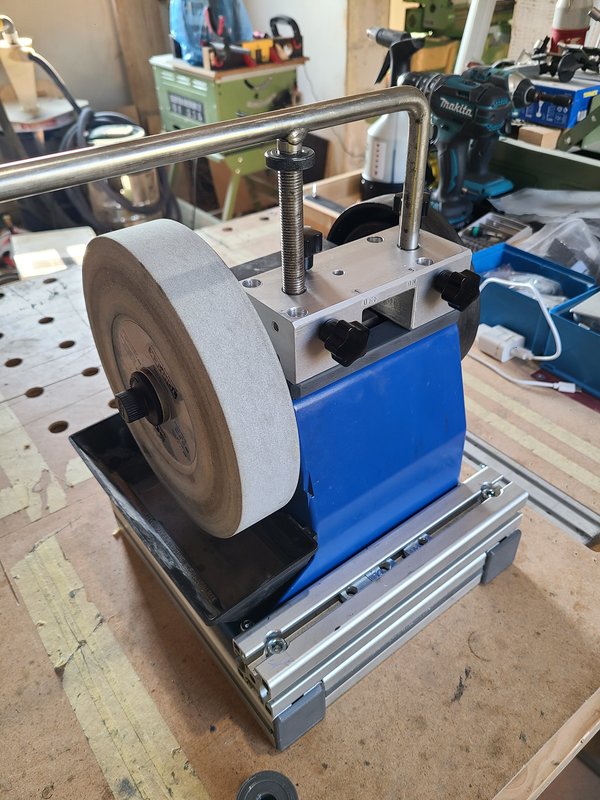
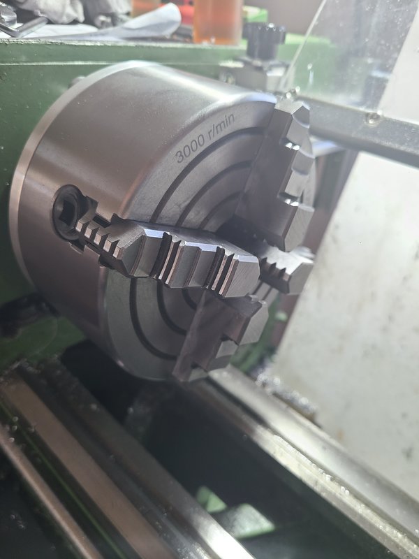
Today, there is a lathe in my workshop. I would therefore make a new set differently, of course.
The pins would be turned from solid stock, properly stepped and faced, drilled on center, and made more consistently. The collar would no longer need to be made from a hammered-on piece of tube, and the cone on the screw could also be machined properly.
I would also take another critical look at the ball-lock principle. After all, the visible pressure marks confirm the objection raised in the forum discussion.
A design with a larger clamping area could be gentler on the fixture plate. Possible approaches might include expansion sleeves, larger pressure elements, or differently shaped clamping jaws.
None of that has been built.
The existing ball-lock clamping pins still do their job. A new principle would therefore need to be more than theoretically better; it would also have to justify the additional manufacturing effort in practice.
I would not throw the old parts away anyway. They show rather well what was already possible before a lathe was available.
Images

Looking Back
This project was made without a lathe and without a milling machine.
The tube and round bar were joined with a sledgehammer, vise jaws served as a stop, a plywood plate became a centering aid, and the cones on the screws were made with an angle grinder clamped in the vise.
The balls were retained in the pins with center-punch marks. PVC hose and hot glue limited the force to what could be applied by hand.
None of these steps is particularly spectacular on its own.
Together, they produced four functional ball-lock clamping pins and ten drop-in stops.
The parts are not perfect. They do not look like purchased components, and they leave light marks.
But they still work today.
That is exactly why they belong on WerkstattDenke.
Not because this is the best imaginable way to make clamping hardware for a welding table.
But because it was the method that worked with the tools and skills I had at the time.
This article documents my specific setup and my experience with occasional use. It is not a general construction, load, or safety guide for welding tables or clamping systems.
How Would You Design the Ball-Lock Mechanism?
The ball-lock clamping pins still work today. The point loading at the edges of the holes remains a compromise that I would examine more critically in a new set.
Do you have experience with ball-lock clamping pins, expansion sleeves, or other clamping devices for perforated welding-table plates? I am especially interested in designs that spread the force over a larger area, can still be operated from above, and can be made with a manageable set of tools.
Long-term experience with pressure marks, wear, and sensibly limited clamping force -as well as well reasoned criticism of my design- is expressly welcome in the comments.
Leave a Reply