
Table of Contents
You know the type, right?
During my apprenticeship, the workshop had the classic Leinen bench vises with 125 mm jaws.
Many years later, I found an old parallel-jaw bench vise with 150 mm jaws in the classifieds.
I thought:
It is only 25 millimeters wider. It not that much bigger.
When the thing was finally sitting in front of me, my first reaction was closer to:
Oh my God. What have I done?
The vise is enormous.
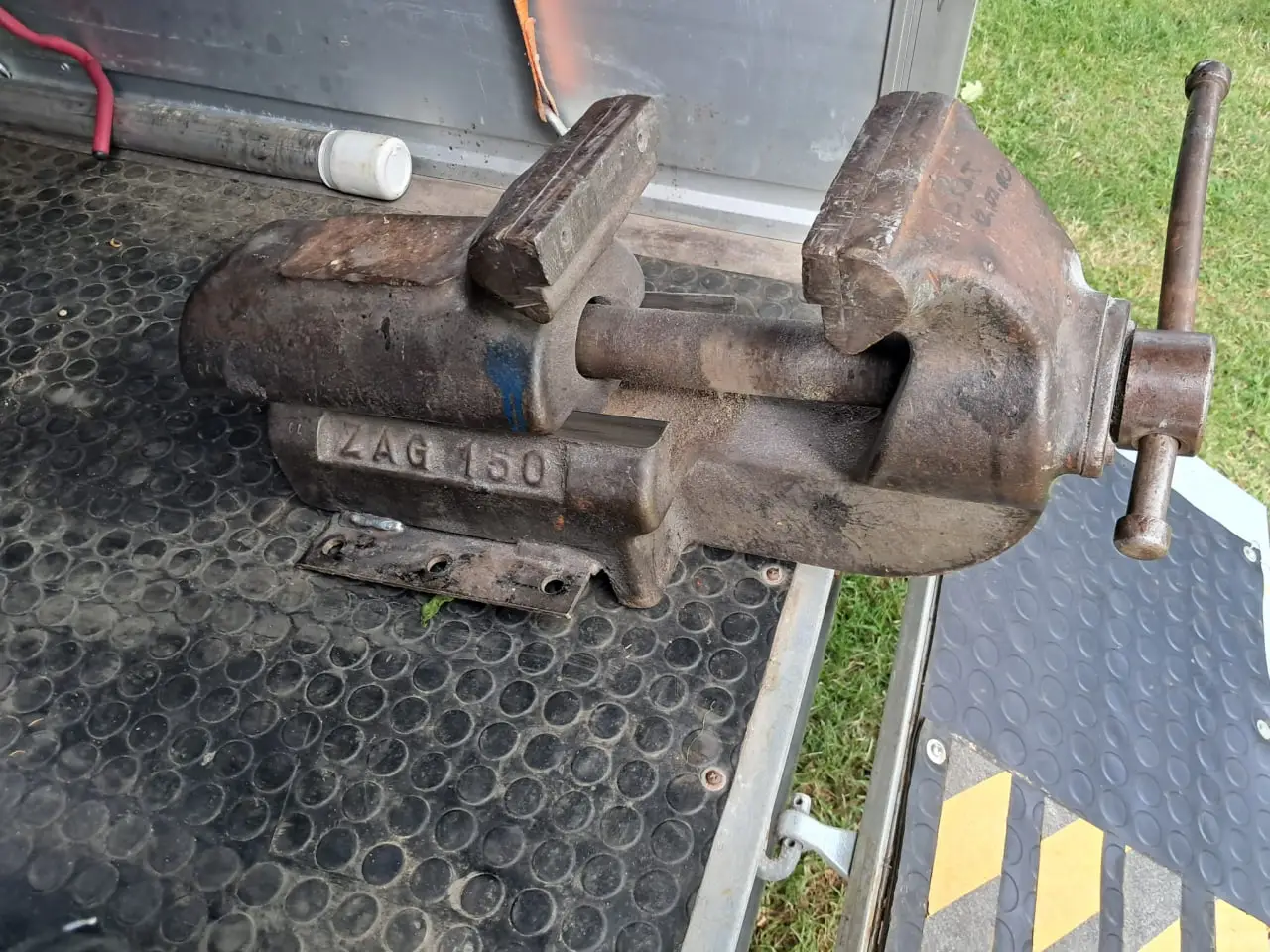
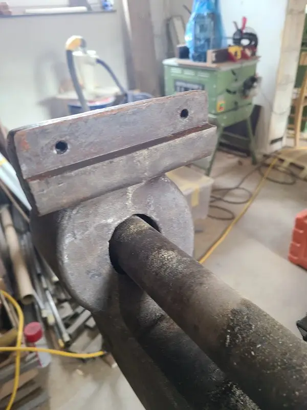
Not only because of the jaw width, but also because of its long slide, massive cast-iron body, and corresponding weight.
Although “weight” is a fairly polite description in this case.
It quickly earned its name:
Little Kunibert.
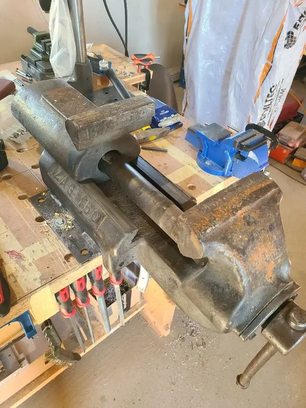
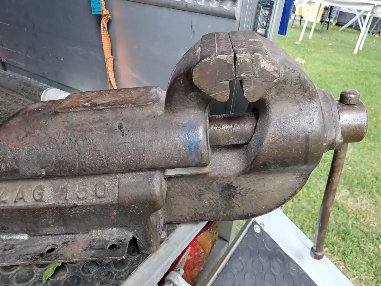
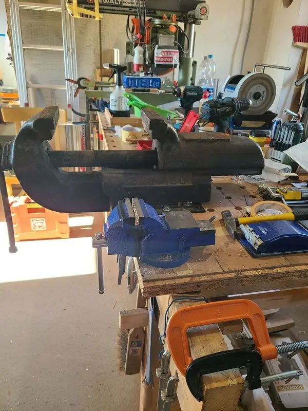
Caption: Little Kunibert as found—rusty, heavy, and considerably larger than an additional 25 millimeters of jaw width would suggest. Beside it is my previous vise for comparison, in blue.
Rusty, heavy, and surprisingly smooth
The exterior was not especially inviting.
It came with:
- rust
- old paint
- dirty slide surfaces
- heavily used jaw plates
- a bent tommy bar
- a questionably welded base plate
- and plenty of evidence of a long working life
Even so, the vise already moved surprisingly smoothly before it had been cleaned or lubricated.
The screw turned easily. The sliding jaw moved through its entire range without sticking.
After several years with much smaller vises from the bargain-basement, hardware-store, and clearance-bin category, I had almost forgotten how pleasant a good parallel-jaw bench vise can be to operate.
And that the word “parallel” in its description is not merely decorative.
There was quite clearly no scrap casting hiding beneath the rust, dirt, and old paint.
The brute gotta stay.
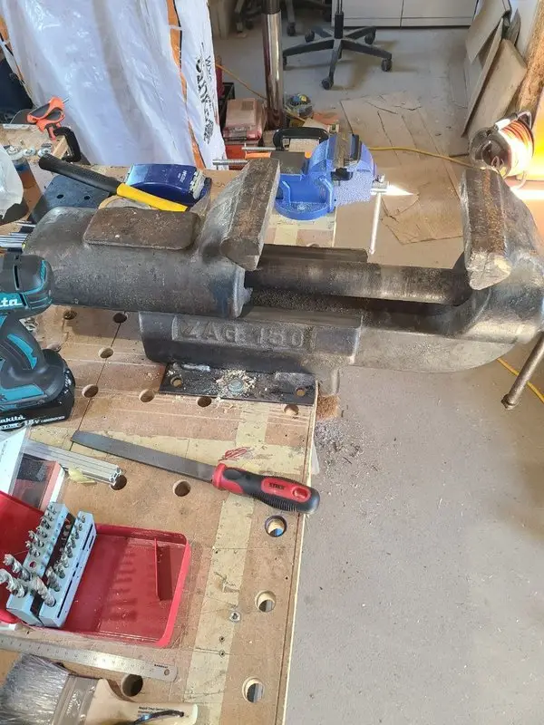
Caption: The long slide and massive cast-iron body quickly made it clear that this vise belongs in a different weight class.
What is a ZAG 150?
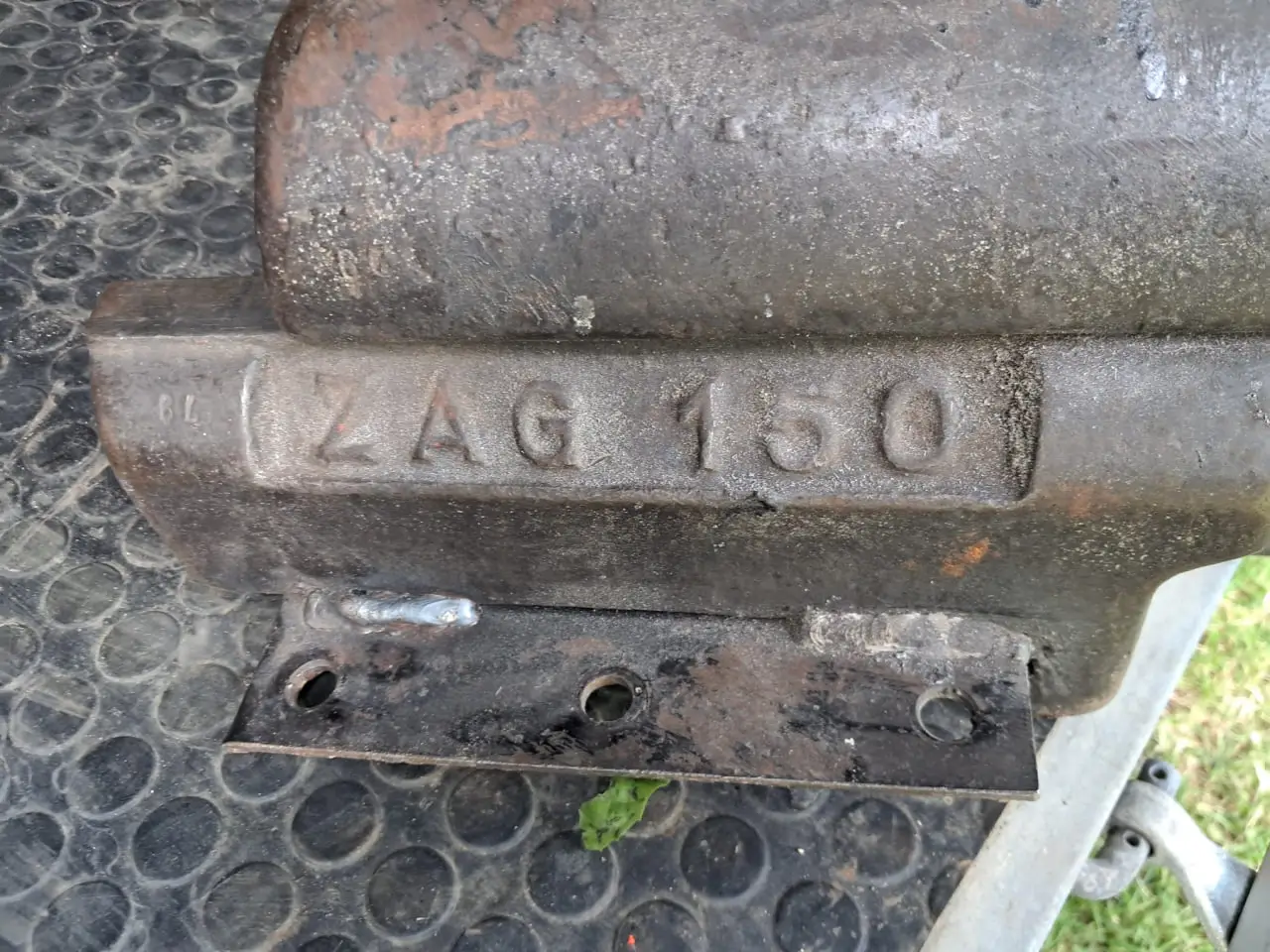
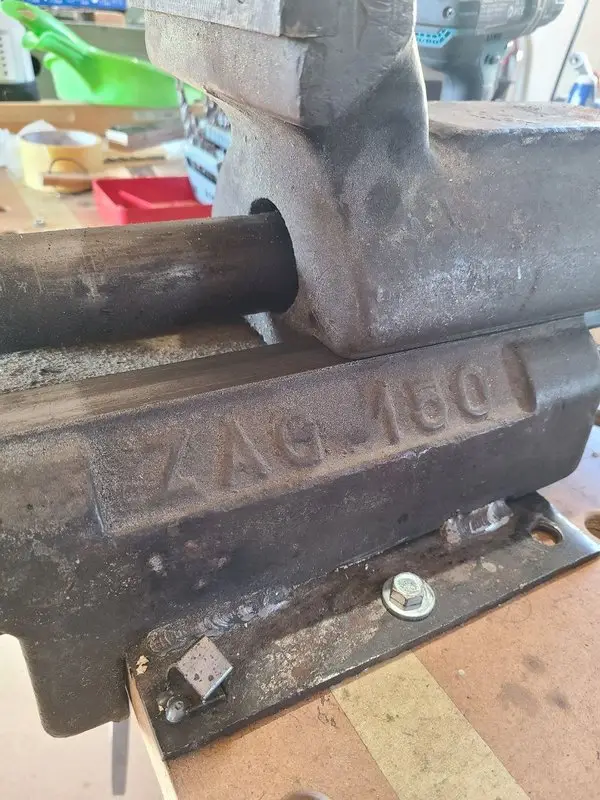
The designation ZAG 150 is cast into the body.
I could find very little reliable information about the brand or manufacturer.
The design resembles older vises made by Leinen, Boley, and other manufacturers.
The forum discussion included the suggestion that ZAG may have originated somewhere in the former Eastern Bloc. I was unable to confirm that.
The vise also carries a stamped 78.
That might indicate a manufacturing year of 1978. It seems plausible, but it remains an assumption.
For that reason, I simply refer to it as a ZAG 150 on this site.
Where and by whom it was actually made remains unknown.

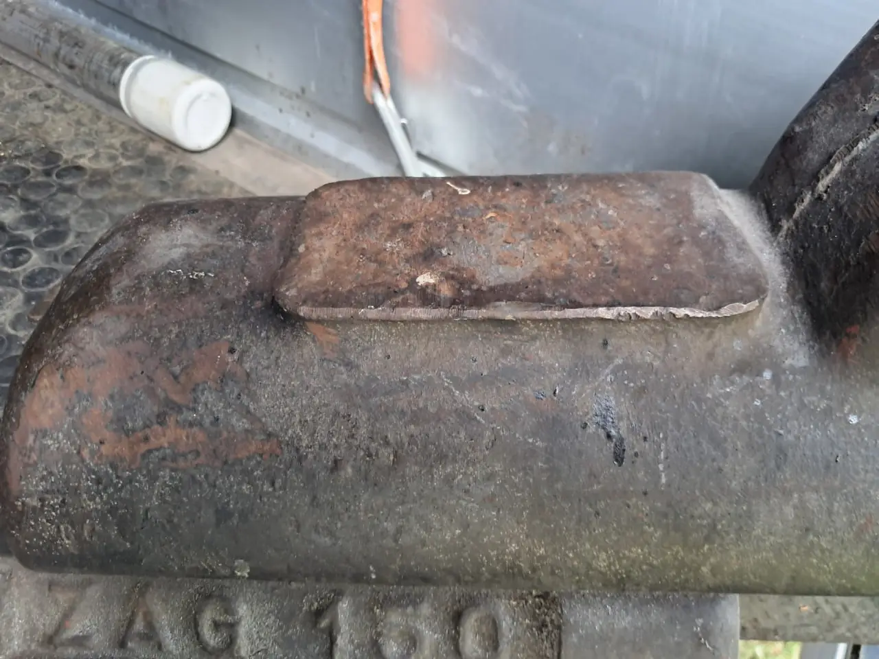
Caption: The ZAG 150 designation is clearly visible in the casting. The steel plate welded underneath was obviously not part of the original design.
The apparent problem with the slide
Besides the rust and old jaw plates, the most obvious issue was the clearance in the sliding jaw.
It lifted visibly when the vise was tightened.
At first, I estimated the movement at roughly 0.2 mm.
My vise had no gib strip or corresponding adjustment screws.
My first thought was therefore:
This really ought to be rebuilt.
With an old tool, the impulse arrives quickly:
- remove the play
- rework the slide
- remachine the surfaces
- adjust everything as tightly and play-free as possible
Before starting any of that, however, I wanted to know how large the supposed problem actually was.
Measure instead of guessing
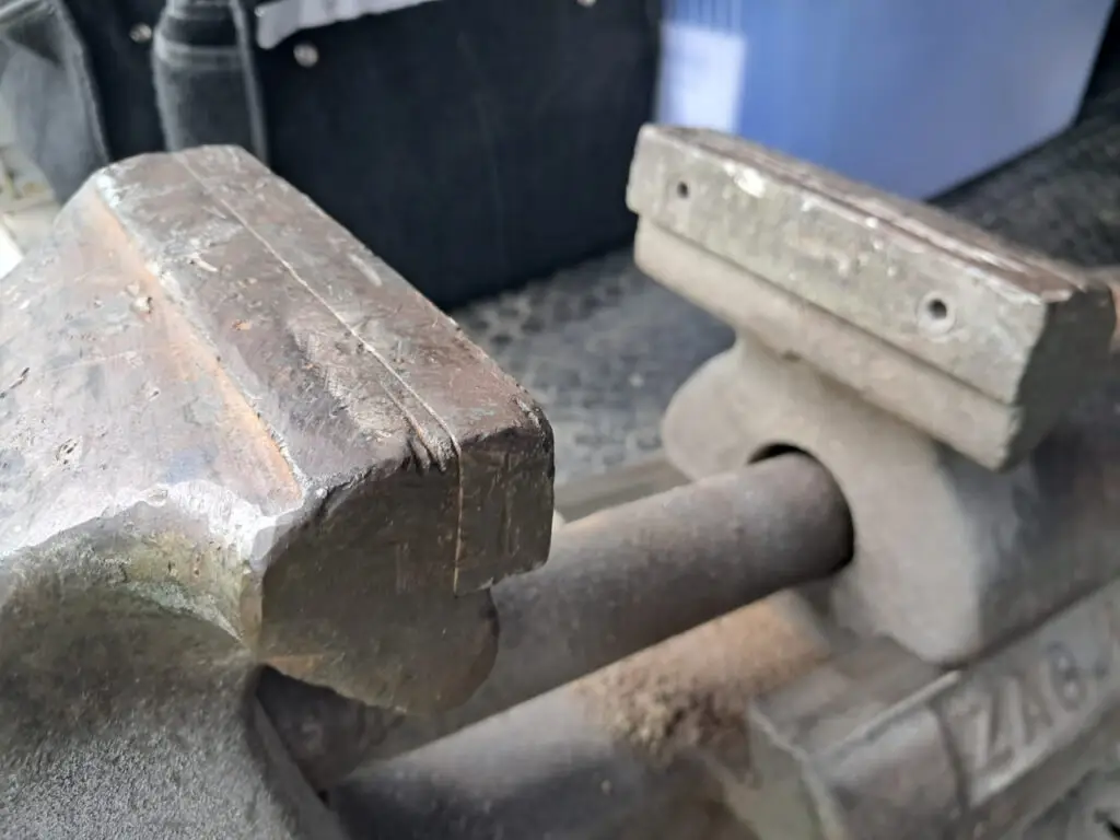
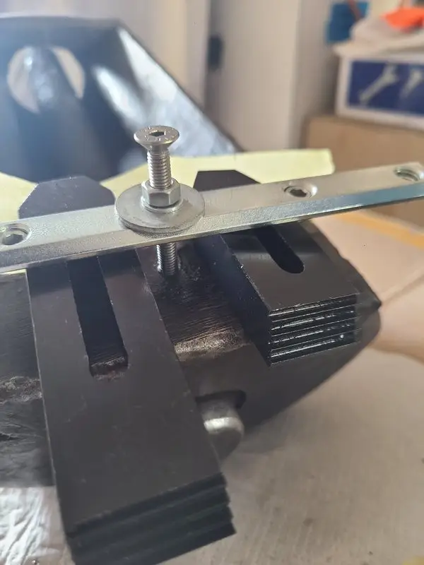
I used a dial indicator to measure the lift of the sliding jaw more accurately.
The measured movement was approximately:
- 0.30 to 0.35 mm
That was slightly more than I had initially estimated.
For a precision or grinding vise, it would be significant.
Little Kunibert is not a machine-tool slide, however. He is a large bench vise.
Similar vises were compared in the forum discussion. On a Boley 125, the sliding jaw also lifted by roughly 0.2 mm under firm clamping pressure.
Noticeable slide clearance was also reported on older Leinen and ZAG-like vises without making their clamping function unusably inaccurate.
More importantly, a practical test showed that Little Kunibert performs his actual job.
Even a small M3 nut can be clamped flat with a slight overhang so that its end face can be worked.
At the same time, the vise can also hold large and heavy workpieces.
The jaw lift is measurable. It does not prevent the vise from functioning.
Not every clearance is automatically a defect
The slide could probably be modified.
That might require:
- measuring the existing surfaces
- reworking worn areas
- remachining the guides
- and making fitted bronze or brass wear strips
That would be a substantial intervention.
It could easily turn a free-moving slide and reliably clamping jaws into a very elaborate project.
Too little clearance could also cause problems:
- The slide could bind when dirty.
- The jaw might no longer move freely.
- Small geometric deviations would no longer be accommodated.
- The rework would have to be extremely accurate.
- The practical usefulness might not improve at all.
I therefore made a deliberate decision:
I am not going to modify the slide merely to make it play-free.
The clearance stayed.
Not because it is ideal, but because the vise performs its job very well.
Understand first, improve second
This became the most important principle of the entire restoration.
An old tool does not automatically need to be returned to as-new condition.
The first questions should be:
- What is actually damaged?
- What is part of the original design?
- Which signs of use affect the function?
- Which areas merely need cleaning and lubrication?
- Which apparent improvement might cause more harm than good?
The restoration was intended to clean, protect, and service Little Kunibert.
It was not intended to redesign him simply on principle.
The welded base plate
A steel plate had been welded underneath the vise.
At first glance, it seemed practical. The plate made it easy to mount the vise to a workbench.
I still did not trust the arrangement.
A large vise can generate considerable forces:
- while clamping
- while sawing
- while bending
- while straightening
- with long workpieces
- and during work involving substantial leverage
The plate itself was probably not the problem.
The critical points were the welded connections between the plate and the vise.
If that connection failed under load, it would not merely drop a small tool from the workbench.
A very heavy vise and possibly the clamped workpiece would come down together.
With a little bad luck, directly onto a foot.
The base plate had to go
I cut off the welded steel plate.
Afterward, my skepticism was confirmed. The connection did not look like something I would have trusted permanently during heavier work.
Removing it was therefore not a cosmetic decision.
The vise would once again be mounted through the points intended by its original design:
- two existing mounting holes at the front
- and one additional hole at the rear
Little Kunibert now sits directly on the workbench.
Three long, substantial wood screws pass through the existing holes in the casting.
The forces now travel directly from the massive body into the workbench.
There is no longer a questionable welded plate in between.
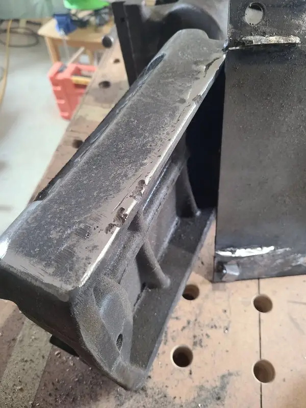
Caption: The later welded base plate was removed. The vise is now mounted directly to the workbench through the existing holes in the casting.
A simple service turns into a restoration
Once it was clear that the vise was staying, I decided to restore it properly.
The plan included:
- disassembly
- cleaning
- rust removal
- inspection of the screw and nut
- fresh lubrication
- painting
- eventually making new jaw plates
- and making a new tommy bar
The goal was not to produce a factory-new vise.
Little Kunibert needed to be mechanically sound, protected, and pleasant to use again.
His working scars were allowed to remain visible.
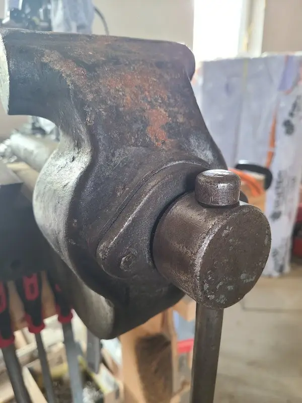
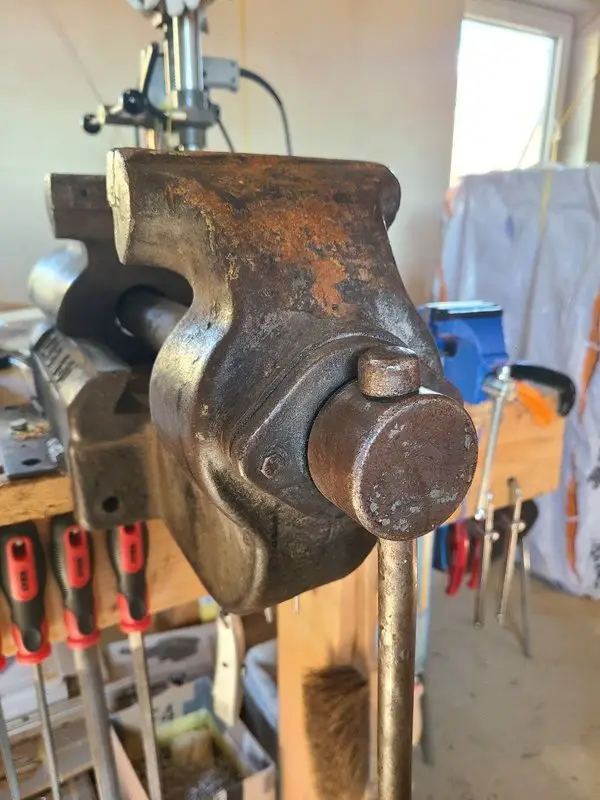
The hidden screw-retaining pin
During disassembly, it was not initially clear how the screw was retained at the front.
Split washers or rings sat beside the screw.
They were loose but could not simply be removed.
There was no obvious screw or clearly visible retaining pin.
A pin eventually appeared beneath the dirt, rust, and old paint.
It simply was not as accessible as I needed it to be.
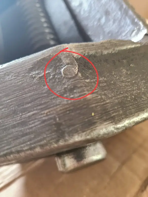
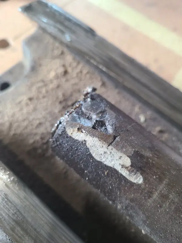
Caption: The retaining pin was initially difficult to identify. Its position is marked in red in the photograph.
The first extraction attempt fails
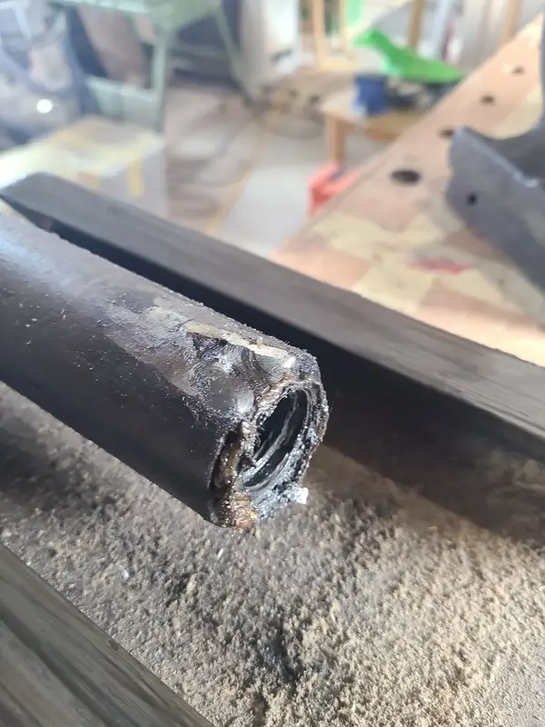
My first plan was to cut an M5 thread into the retaining pin.
I then intended to pull the pin out using a screw and a simple improvised puller.
It did not work.
The thread stripped. The pin remained where it was.
I still had a stuck retaining pin, but now it contained slightly less useful material.
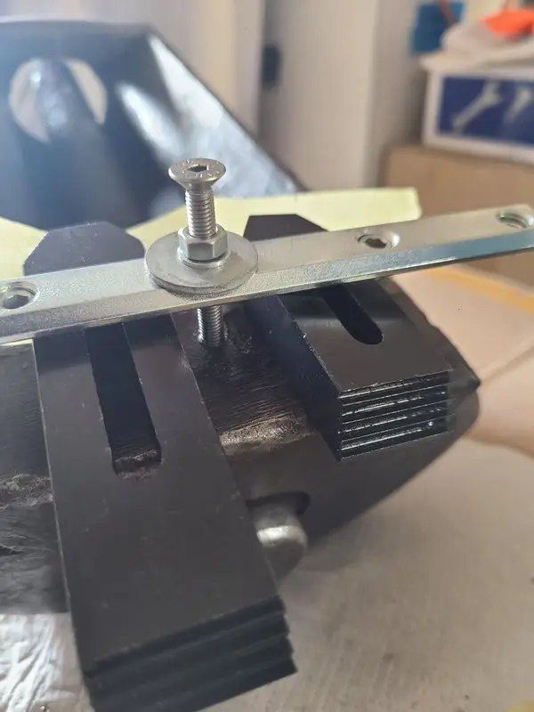
Caption: The first attempt was supposed to extract the pin through an M5 thread cut into the pin itself. The thread gave way. The pin did not.
Drilling through and installing a new pin
In the end, I chose a more pragmatic solution.
I drilled a 6 mm hole completely through the area.
This allowed the old connection to be removed completely and replaced with a new pin later.
It no longer matches the original construction.
It is, however:
- unambiguous
- accessible
- safe to assemble and disassemble
- and easy to understand during a future service
Not every old pin has to be saved at any cost during a restoration.
What mattered more was being able to remove the screw completely and rebuild the connection reliably afterward.
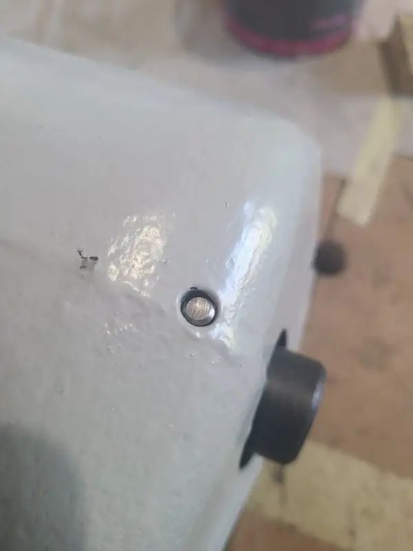
Caption: After drilling through, the connection was rebuilt with a new externally accessible pin that can be driven out downward.
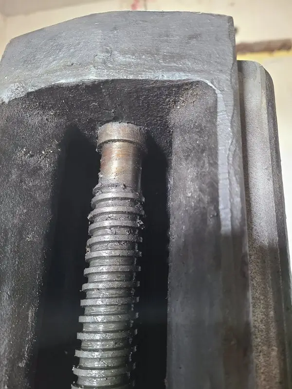
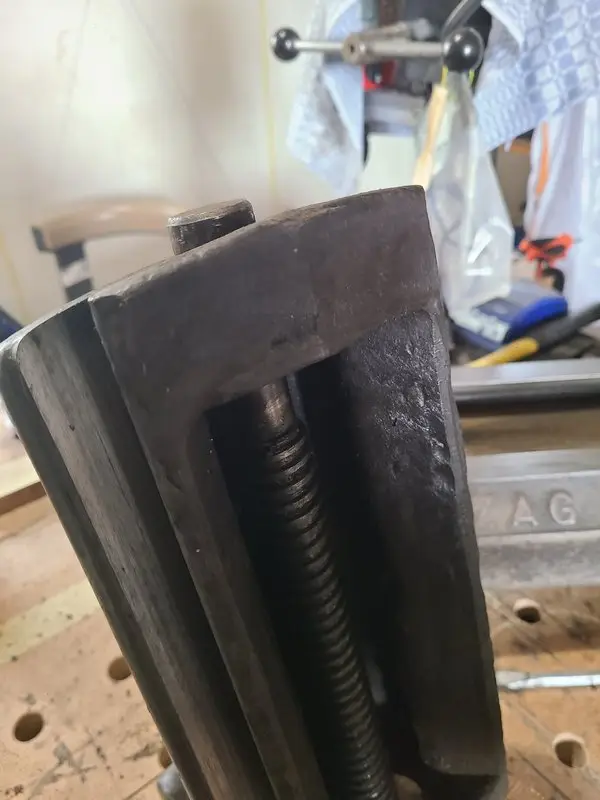
The screw and nut
Once the retaining arrangement had been released, the screw could be removed completely.
This also provided access to areas that would have remained hidden during a superficial cleaning.
The screw was:
- cleaned of old grease and dirt
- inspected for visible damage
- cleaned thoroughly
- and lubricated with fresh grease
The corresponding internal areas of the vise were cleaned as well.
The screw and nut were not the actual reason for the restoration. The vise had already run surprisingly well.
The service simply removed the old contamination and renewed the lubrication.
After reassembly, Little Kunibert moved at least as smoothly as before.
Only cleaner.

Caption: Only after complete disassembly were the screw, thread, and previously hidden internal surfaces accessible.
Removing rust and old paint
I cleaned the cast-iron body using:
- a cup brush
- an angle grinder with a wire wheel
- and a hand-held wire brush
The powered brushes made it possible to clean the larger areas more quickly.
They removed loose rust, poorly adhering paint, dirt, and unstable coatings.
The hand brush was better in corners, recesses, and more sensitive areas.
The cast-iron body was not meant to be ground perfectly smooth or polished bright.
The aim was to remove loose material and create a sound surface for the new paint.
The texture of the casting and many old working marks remained visible.
Not factory-new
A great deal of time can be spent making every surface of an old tool perfectly smooth.
That was not my goal.
Little Kunibert is a working tool.
The new coating was intended to:
- protect against further rust
- make cleaning easier
- give the vise a more coherent appearance
- and make it presentable again
The surface needed to be clean and stable.
It did not need to look new, or as though the vise had never been used.
Anthracite and light gray
The prepared casting was first primed with anthracite 3-in-1 rust-protection paint.
A light-gray topcoat followed, also using 3-in-1 rust-protection paint.
The color choice was not based on historical research into the original ZAG finish.
The paint was simply already there.
The lighter gray also made the already enormous vise appear slightly less massive.
At least in theory.
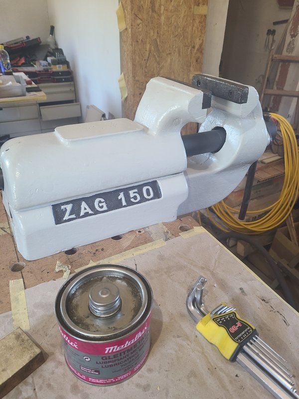
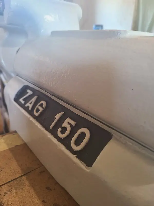
The ZAG 150 designation was highlighted again afterward.
Despite the new paint, it therefore remains clear which vise is hiding underneath it. I also happen to like the visual detail.
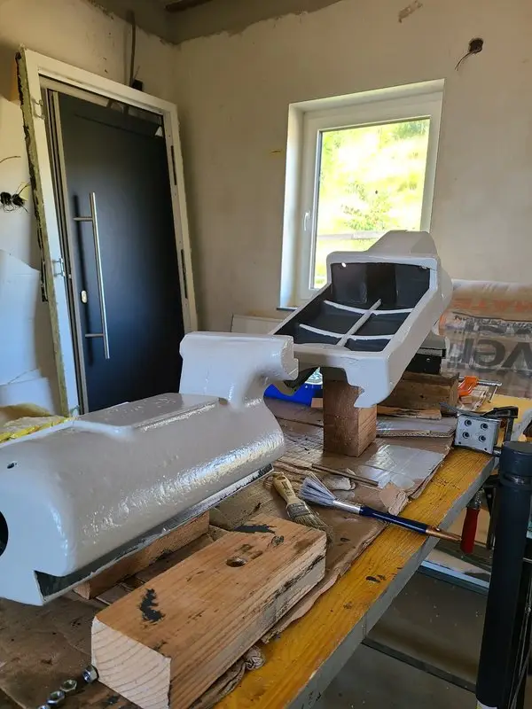
Caption: Primed in anthracite and painted light gray. The paint was already available and was intended to make the massive casting look at least slightly lighter.
Working surfaces remain working surfaces
Not every area was painted.
Slide surfaces, moving areas, and other contact points obviously do not need a decorative coating.
What matters there is:
- cleanliness
- appropriate lubrication
- unrestricted movement
- and direct metal-to-metal contact where the design requires it
Paint on a slide surface. Brilliant idea.
The relevant surfaces were therefore left bare, masked during painting, or scraped clean again afterward.
The anvil pad
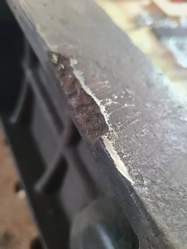
Behind the fixed jaw, the vise has a larger flat area that can serve as an anvil pad.
The surface had seen considerable use.
I cleaned it and reworked it with the tools available until it looked respectable again and remained useful for light work.
It was not completely remachined.
There was no particular reason to do so.
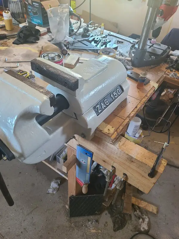
Caption: The anvil pad was cleaned and lightly reworked. Old marks remained because complete remachining was not functionally necessary. In the background: chaos.
Not a forging anvil
Some restraint is sensible when using this surface.
The vise is made of cast iron.
Cast iron can withstand high compressive loads and plenty of ordinary workshop use.
Hard impact loads are a different matter.
Heavy forging or severe hammer blows could crack the casting.
I therefore do not treat the pad like a forged anvil.
It is useful for:
- light straightening
- small assembly work
- careful support work
- and controlled light hammering
A thick steel plate is within reach for heavier work anyway.
The old jaw plates
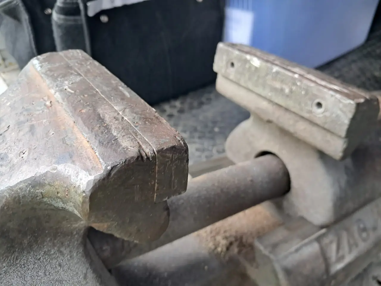
The existing jaw plates show obvious signs of use.
They are worn, damaged, and visually far from new.
They still work.
Small parts can be held just as securely as larger workpieces.
New jaw plates are still planned.
Cold-drawn C45 flat stock was ordered and delivered for the job.
Part of that material received another assignment in the meantime.
It was needed for the screw support during the conversion of the Emcomat cross slide to a TR10×2 screw.
That is how workshop material sometimes moves from the planned project to the one that has become more urgent.
Why make custom jaw plates?
With an old vise of unknown origin, there is no guarantee that suitable replacement jaws can be purchased.
Even when the length and height match, the following may differ:
- hole spacing
- hole positions
- screw sizes
- counterbores or countersinks
- and distances from the edges
If the new hole pattern overlaps the existing holes unfavorably, adapting unrelated jaw plates may be impractical.
Because the manufacturer of the ZAG 150 remains uncertain, making custom jaws from C45 appears to be the sensible solution.
They can therefore be made directly to match the existing mounting points.
Smooth or serrated?
The final design of the new jaw plates is still undecided.
Possible versions include:
- smooth steel jaws
- serrated jaws
- a separate set of each
- or additional soft jaw covers
Serrations improve grip but mark the workpiece more readily.
Smooth steel jaws would be sufficient for much of my work.
Additional protective jaws can be used for delicate parts.
Because the existing jaws still work, there is no urgency.
The raw material is ready.
The jaws will be made when they eventually reach the front of the queue.
The bent tommy bar
The tommy bar also shows that the vise was not always treated gently in its previous life.
It is bent.
A replacement is planned, and suitable material is already available.
The old bar is still installed, however.
It works.
A new straight bar would look better and would probably be more pleasant to use.
It is not currently necessary for the vise’s actual clamping performance.
Reassembly
After cleaning, painting, and servicing the screw, Little Kunibert was reassembled.
The finished assembly included:
- the cleaned and painted cast-iron body
- the cleaned and freshly greased screw
- clean slide surfaces
- the new retaining pin
- the existing jaw plates
- the old bent tommy bar
- and direct mounting to the workbench
The vise had already moved almost effortlessly before the restoration.
After the service, the movement feels clean and controlled.
The sliding jaw moves pleasantly across its long range.
When tightened, the massive construction has exactly the calm, solid feel I remembered from the old parallel-jaw vises used during my apprenticeship.
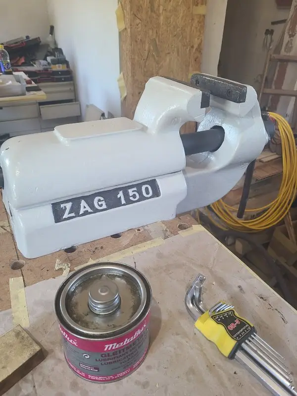
Caption: Little Kunibert after the restoration—serviced, repainted, and mounted directly through the existing holes in the casting.
The new working height
Because of its size, the clamping point sits considerably higher than it did on my previous small vise.
This is particularly comfortable when filing or sawing.
The workpiece sits at a useful height without requiring me to bend down unnecessarily.
Little Kunibert takes up space.
In return, his size also improves the working position.
From M3 to heavy work
Everyday use reveals the vise’s real strength.
It is not limited to large workpieces.
Small parts can also be held sensibly.
An M3 nut, for example, can be clamped flat with the surface to be worked projecting slightly above the jaws.
At the opposite end of the scale, Little Kunibert accepts much larger parts.
I use it for tasks including:
- sheet metal
- sections and profiles
- round stock
- larger assemblies
- heavy workpieces
- straightening work
- assembly work
- and occasional pressing jobs
Finally, a parallel-jaw bench vise that simply works.
Caption: A direct size comparison explains better than any measurement why the ZAG 150 quickly became Little Kunibert.
The slide clearance in everyday use
The measured lift of the sliding jaw is still present.
In normal use, it hardly matters.
Workpieces are held securely. Small parts do not slip out. Large parts can be clamped firmly.
At the same time, the jaw moves freely enough to travel across its long range without unnecessary effort.
The decision not to rebuild the slide prematurely was therefore the right one.
The clearance is measurable. It does not prevent the vise from working.
What was deliberately left unchanged
Several points were intentionally not reworked:
- the slide clearance
- the existing guide geometry
- the old jaw plates
- the bent tommy bar
- the anvil pad, which was not completely remachined
Not because these areas are perfect.
They simply do not currently interfere seriously with the use of the vise.
A restoration does not have to remove every working mark and every characteristic of the original construction.
Sometimes the most sensible approach is:
Clean it, service it, protect it, and then use it for a while.
What is still planned
The remaining list still includes:
- new C45 jaw plates
- a new straight tommy bar
- possibly more accurate machining of the anvil pad
- and perhaps suitable protective or auxiliary jaws
The slide will probably remain unchanged.
Fundamental rework would make sense only if a real problem appeared during use.
So far, there is no reason for it.
What I would do differently today
The restoration worked.
Even so, I would approach a few steps differently today.
Inspect the base plate earlier
The welded plate initially looked like a practical addition.
On a vise this heavy, however, any later mounting modification should be inspected critically before the vise is placed into service.
Expose the retaining pin completely
The first attempt using the M5 thread failed.
With better access and a clearer view of the retention method, I might have recognized earlier that drilling through and installing a new pin was the more direct route.
Decide on unfinished work before painting
New jaw plates and a new tommy bar were already planned, but they were not completed at the same time.
That is not a functional problem.
During a fully planned restoration, all remaining work could be completed before painting and final assembly.
Still avoid repairing too much
I would make the most important decision exactly the same way again.
I still would not automatically try to eliminate all clearance from the slide.
It would involve a great deal of work.
And it might not be an improvement.
Current state
Little Kunibert has been restored, mounted, and placed into service.
He now has:
- a cleaned and painted cast-iron body
- a completely cleaned and freshly greased screw
- clean slide surfaces
- a new retaining pin
- solid direct mounting to the workbench
- the existing jaw plates
- and the same bent tommy bar
The remaining jobs are:
- new C45 jaw plates
- a new tommy bar
- and possible later work on the anvil pad
The vise does not have to wait for any of those jobs.
It already works extremely well.
Looking back
What initially looked like an oversized rusty mistake became one of the most pleasant tools on my workbench.
Little Kunibert arrived:
- rusty
- neglected
- with old jaw plates
- with a bent tommy bar
- with a questionable base plate
- and with measurable slide clearance
Even so, it moved smoothly from the very first day.
The most important part of the work was therefore not rebuilding it completely.
It was finding out:
- What is actually damaged?
- What belongs to the original design?
- Which area needs servicing?
- Which modification would genuinely improve something?
- Which apparent defect is better left alone?
The slide stayed as it was.
The screw was cleaned and freshly greased.
The questionable base plate disappeared.
The rust was removed.
The casting received a new coating.
And a dark, heavy lump became a light-gray lump that was still every bit as heavy.
Only now it is one that is genuinely enjoyable to work with.
Image gallery










Forum discussion (German)
The assessment of the slide clearance and the decision not to modify it prematurely were influenced by the forum discussion.
The discussion included:
- comparisons with similar Boley and Leinen vises
- measurements of sliding-jaw lift
- possible methods of reworking the slide
- material suggestions for new jaw plates
- and discussion of the unknown origin of ZAG
The origin of the vise could not be established conclusively there either.
Forum discussion: ZAG 150 parallel-jaw bench vise
Leave the slide clearance alone—or rework it?
The sliding jaw lifts by approximately 0.30 to 0.35 mm. The movement is easy to measure, yet Little Kunibert still runs smoothly and holds both small and heavy workpieces reliably.
Have you restored or used a similarly constructed ZAG, Leinen, Boley, or another older parallel-jaw bench vise over a longer period?
I would be particularly interested in whether comparable slide clearance caused real problems during long-term use—or whether reworking the slide introduced more new difficulties than improvements.
Reasoned criticism and alternative solutions are also welcome, especially regarding custom C45 jaw plates, smooth versus serrated gripping surfaces, and other ways of replacing the hidden screw-retaining pin.
This article documents the restoration of my specific vise and my experience using it. Old cast-iron tools may contain hidden damage. Mounting points, cracks, guide surfaces, and load-bearing connections must be assessed independently before the tool is placed under load.
Carriage Stop for the Emcomat 8.6 — Built on the Slow-Shaper Lathe
Leave a Reply