
Table of Contents
DUSS KB43 with a Belated Euro-Conversion
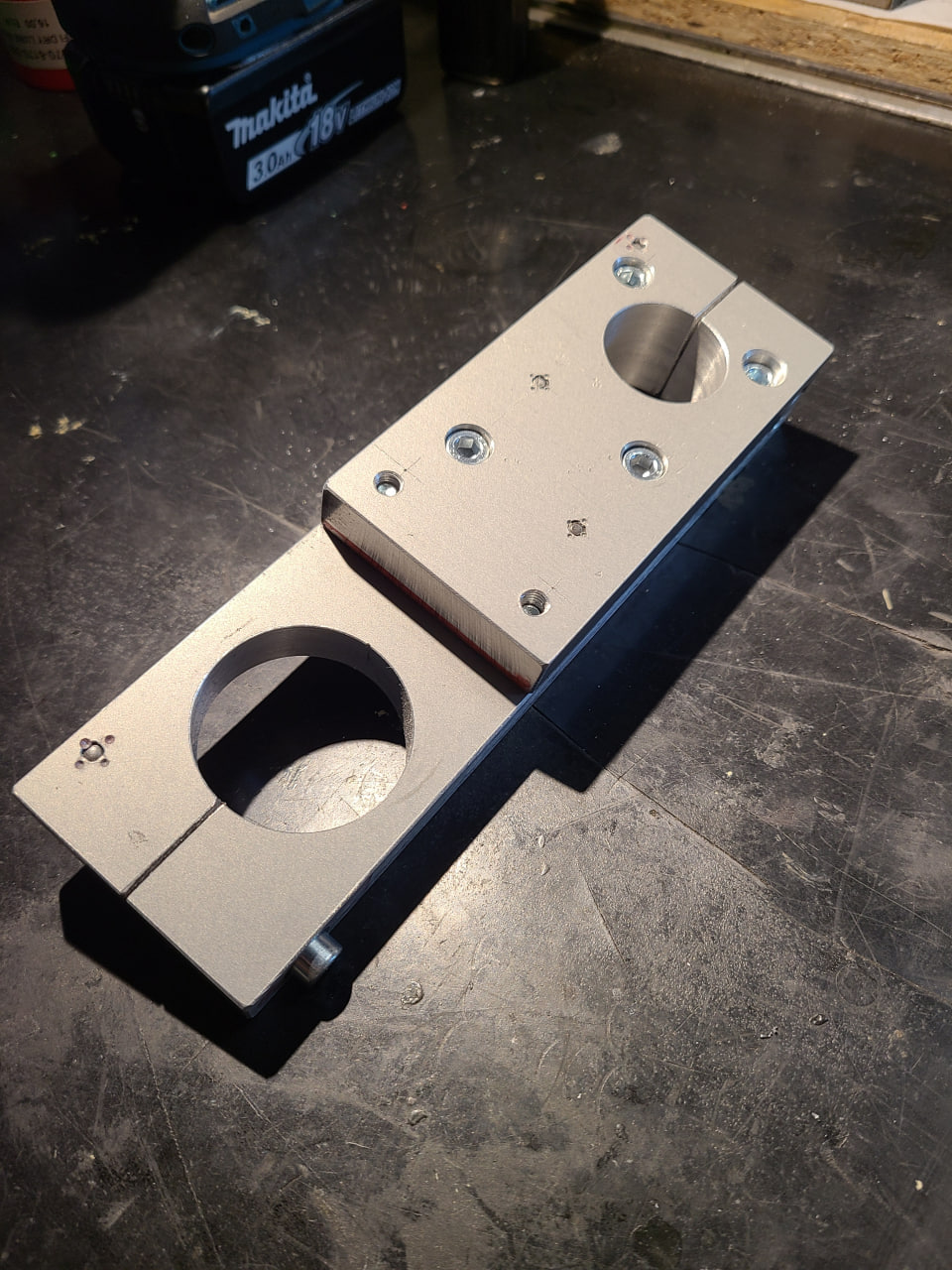
My DUSS KB43 drill stand has a quill with a diameter of 30 millimeters. A suitable tool holder was not included – only some kind of special mount that was of little use to me.
I wanted to mount a normal drill or other tools with a 43 mm Euro collar.
What I needed was therefore a holder with:
- 30 millimeters on the drill-stand side
- and 43 millimeters on the tool side
I did not have a lathe or a milling machine.
But I did have several aluminum plates, a vise, a boring head, the DUSS KB43 drill stand, and a holder I had previously built for my father’s large Fein drill.
That turned this into another one of those chicken-and-egg projects:
To expand the drill stand, I had to build a holder.
To build that holder, I needed a holder – which, fortunately, I had already built.
The new mount was therefore not only made for the drill stand.
It was also made with it.
What the Holder Needed to Do
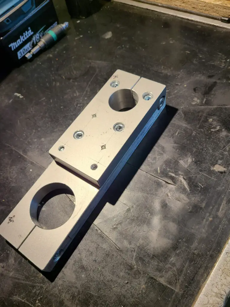
On one side, the holder had to slide onto the 30 mm quill of the DUSS KB43 and clamp securely in place.
On the other side, it had to accept a machine with a 43 mm Euro collar.
Originally, that was mainly my Fein BOP 6. Unfortunately, this much-appreciated drill later went up in smoke and was replaced by a DUSS B13. It ought to feel at home in that saddle.
The holder could still be used, of course. With an adapter, I can also occasionally mount a Proxxon IB/E rotary tool in it.
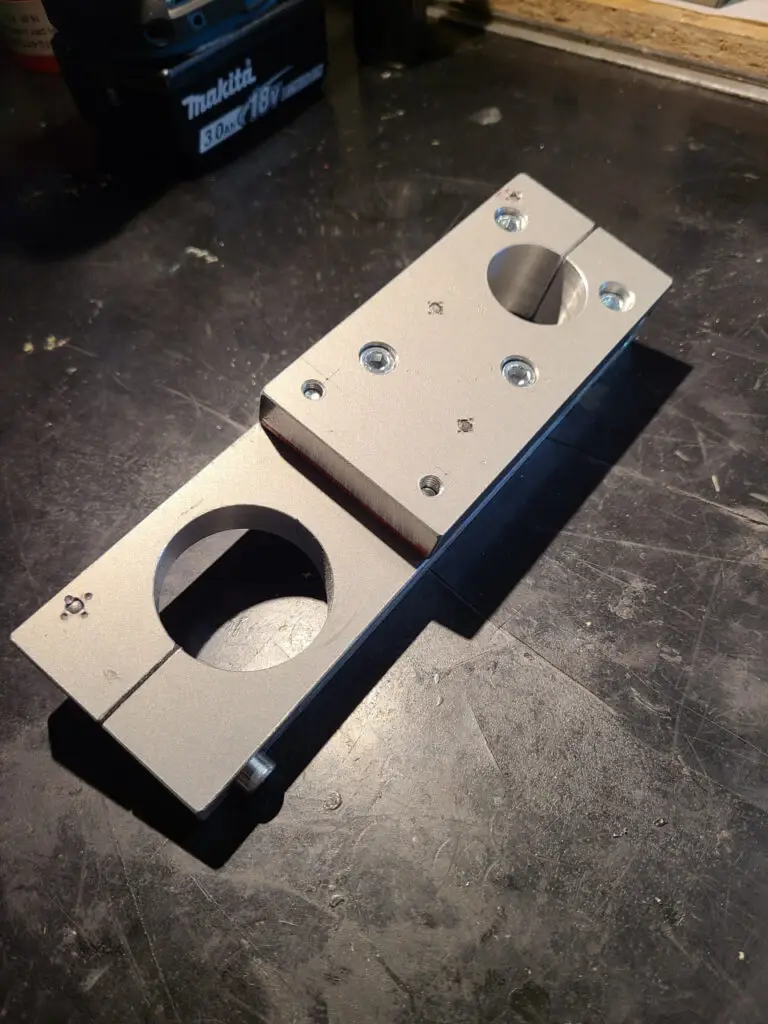
The holder is basically just a plate between two existing diameters. The real challenge was making both mounting bores accurate enough to fit and clamp properly.
Construction from Aluminum Plates
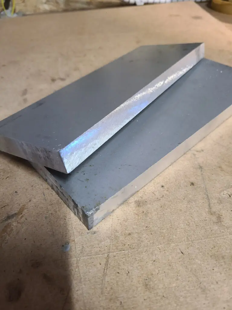
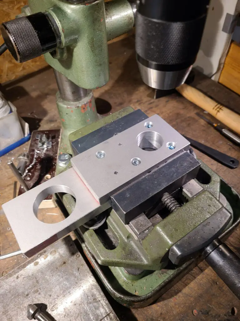
I used 15-millimeter-thick aluminum plates as the starting material.
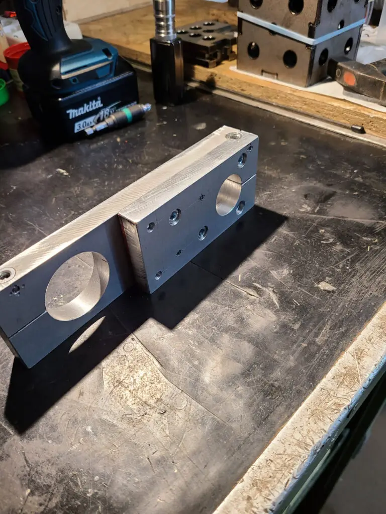
The long main section is approximately 200 millimeters long, 60 millimeters wide, and 15 millimeters thick.
A second plate was added around the 30 mm quill clamp. This created a thicker block in that area while the rest of the holder remained comparatively flat.
With a milling machine, I probably would have made the holder from a suitable solid block.
I simply did not have one.
The multi-part construction did have several advantages:
- I could use the plate material I already had.
- A large solid block of aluminum was not necessary.
- The design could be built up step by step.
- Some holes remained accessible from both sides.
- Screws, dowel pins, and threaded couplers could be easily accommodated between the plates.
A Sketch Had to Be Enough
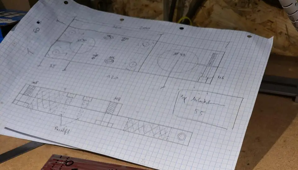
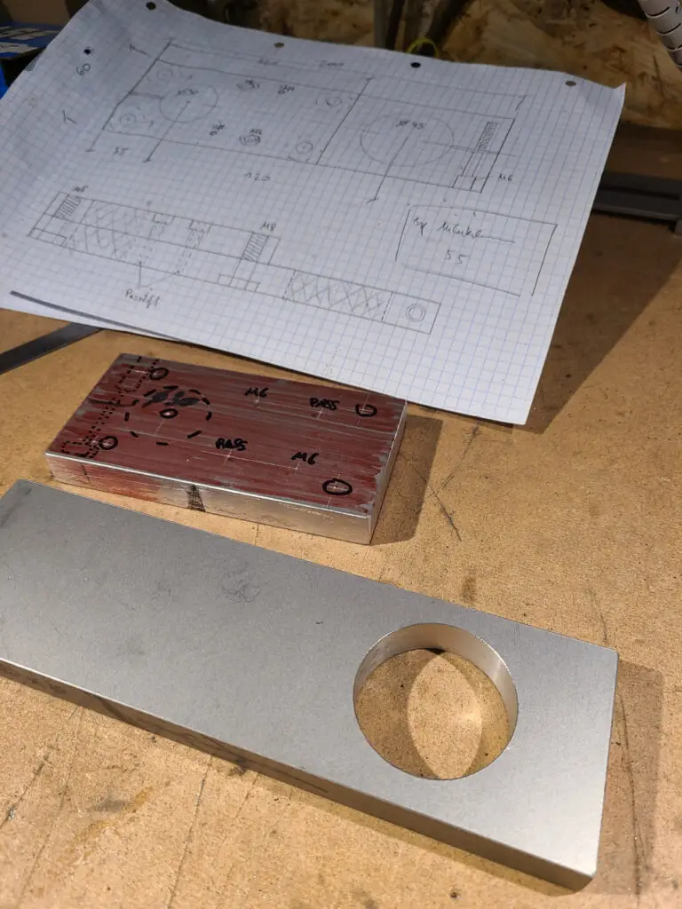
As with many of my projects, it began with a quick hand sketch only.
It showed the positions of the two mounting bores, several important distances, the screws, dowel pins, clamping holes, and saw cuts.
It was not a complete technical drawing.
It only had to keep me from having to work out every dimension again while drilling.
Part of the final design only emerged while I was working with the material that was actually available.
One Fixture Builds the Next
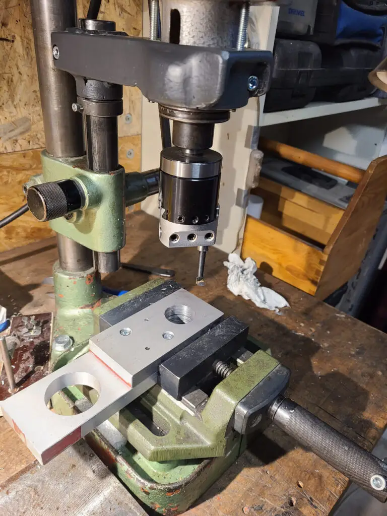
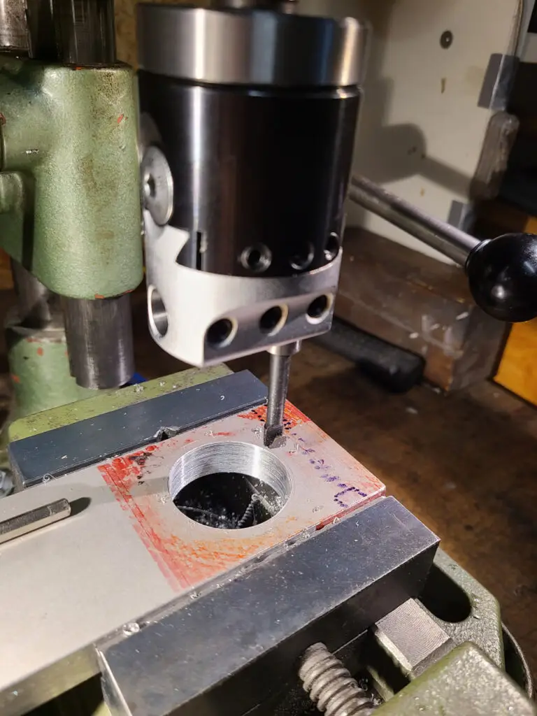
I wanted to make the two large mounting bores with a boring head.
For that, I had:
- a simple boring head
- a Fein geared drill with an MT2 socket
- the DUSS KB43 drill stand
- and a holder I had previously built for my father’s large Fein drill
The fixture that made it possible to build the next fixture.
The old Fein holder still exists and deserves its own documentation someday. For this project, it was simply the tool I already had – and the one I needed.
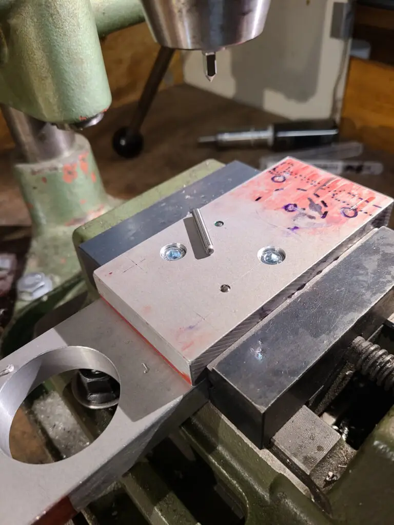
Aligning, Bolting, and Dowel-Pinning the Plates
Before boring, the individual aluminum plates had to be joined firmly together.
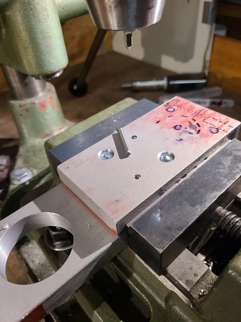
The screws hold the plates together. Additional dowel pins prevent them from shifting relative to one another.
They also allow the holder to be reassembled in the same position after it has been taken apart.
This was particularly important when the plates were bored together. During machining, the multi-part assembly needed to behave as much like a single workpiece as possible.

Pilot Drilling and Boring
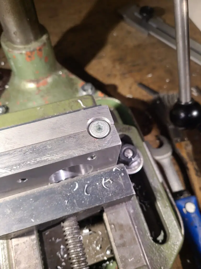
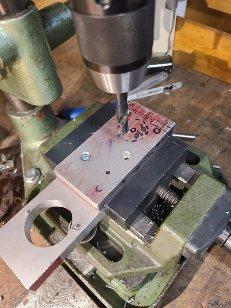
Before boring, I removed as much material as possible with ordinary drills and a hole saw.
The pilot holes did not need to match the final diameter. They only had to provide enough room for the boring tool and reduce the amount of material that still had to be removed.
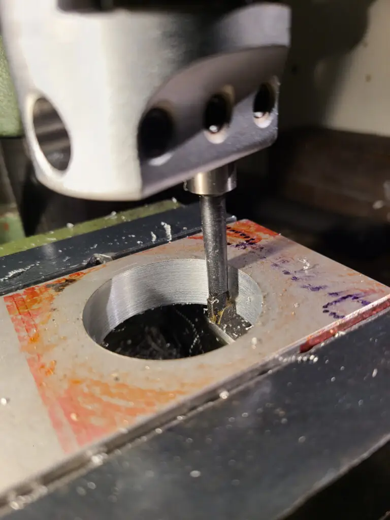
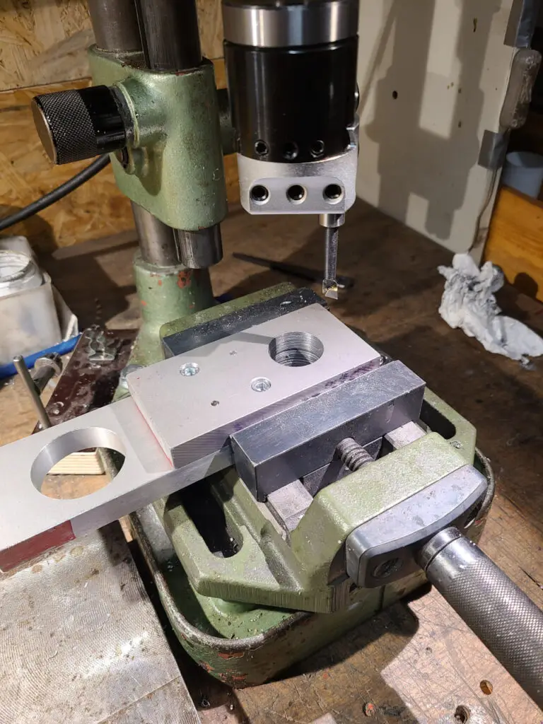
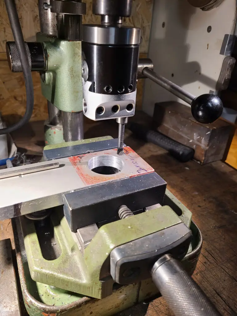
The workpiece was then clamped in the vise on the drill stand. The boring head was mounted in the Fein drill.
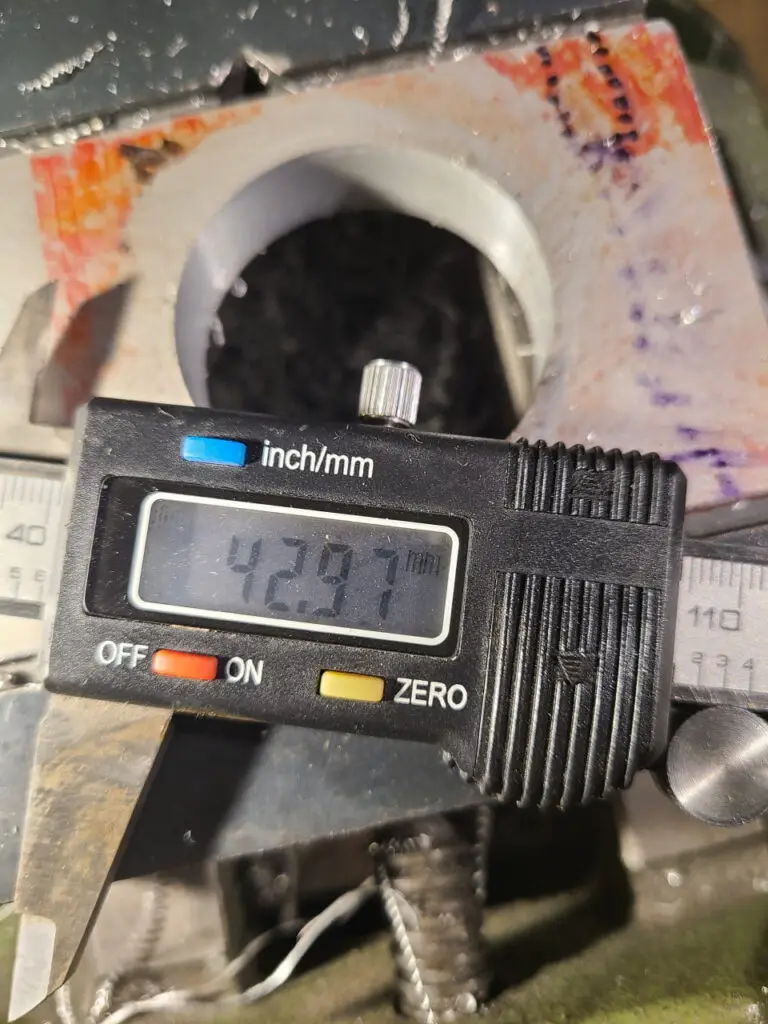
By increasing the setting a little at a time, I eventually produced:
- 30 millimeters for the quill of the drill stand
- 43 millimeters for the Euro collar of the drill
The advantage of the boring head was that I could gradually approach the dimensions of the actual mating parts.
A hole that was too small could still be opened further.
A hole that was too large would have been much harder to correct.
The 43 mm mount for the Fein BOP 6 in particular ended up fitting very closely.
Critical: MT2 Without Retention or a Drawbar
Both the boring head and the spindle of the Fein drill used a Morse taper: MT2.
A Morse taper normally holds very well under axial load. A boring head, however, places significant lateral forces on the tool.
My setup did not have a drawbar.
There was therefore a risk that the rotating boring head could work loose from its seat during machining.
My solution at the time was correspondingly rustic.
I made a suitable driver from M10 stock to engage the taper tang and filed it to the required shape. A set screw in an angled threaded hole then braced and clamped the connection in the spindle’s cross hole.
The retention device remained removable and worked for this particular setup.
Not recommended for replication.
Today, I would use a toolholder with a proper axial retention system or drawbar.
A Morse taper that is held only by friction and secured with an improvised device must be viewed very critically when used with a boring head (or any lateral force).
Clamping with a Saw Cut
After boring, both mounting holes still had to be made clampable.
For each one, I cut from the outside edge into the bore.
When the clamping screw is tightened, the slotted aluminum can deform slightly. This closes the mount around the quill or Euro collar.
A separate clamping jaw was not necessary.
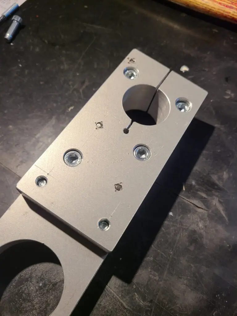
Later, someone in the forum discussion suggested extending the saw cut a little beyond the opposite side of the bore.
This would allow the clamping area to conform over a larger region instead of mainly deforming directly at the open end.
I made this change on the 30 mm quill side. The slot was extended beyond the bore and finished with a small relief hole.
I left the 43 mm mount unchanged. It already fitted the collar of the Fein BOP 6 very closely and required only a small amount of deformation to clamp it.
Forum discussion (German): DIY tool holder with 30 mm and 43 mm Euro-collar mounts
Replaceable Steel Threads
I needed durable threads for the two clamps.
Threads cut directly into the aluminum would also have worked initially. With repeated opening and closing, however, they could have become wear points.
I therefore used M6 and M8 steel coupling nuts or threaded sleeves.
They sit transversely in matching holes in the holder. An additional radial pin prevents each sleeve from turning when the clamping screw is operated.
Should one of the threads become damaged, the sleeve can be replaced. The aluminum holder itself would not have to be rebuilt.
No replacement has been necessary so far.
A repair option is useful even when it is never needed.
Mounting and Lever Arm
The holder slides onto the quill with its 30 mm mount and is clamped in place.
The actual drill is mounted in the 43 mm opening.
This places the tool centerline noticeably outside the quill axis, creating a corresponding lever arm.
As a result, play in the quill, flexibility in the aluminum plates, compliance in the clamping points, and machining forces have a greater effect than they would with a machine positioned directly beneath the quill.
For my normal drilling work, the construction is sufficiently rigid.
“Sufficiently rigid,” however, is not the same as “incapable of improvement.”
What Has Proven Itself in Use
The holder has been in use for years.
So far, there have been:
- no noticeably worn mounting surfaces
- no stripped threads
- no replaced threaded sleeves
- no retrofitted bushings
- no unreliable quill clamping
- and no necessary repairs
The Fein BOP 6 that was originally used has since failed. Thanks to the 43 mm Euro-collar mount, the holder remained usable.
Today, the DUSS B13 is normally installed. Occasionally, I also use the Proxxon IB/E.
The drill usually remains in the holder, so tool changes are relatively rare.
The bushings I originally considered were never installed either. In my use, the direct contact between the steel quill or tool collar and the aluminum has not shown any significant wear.
That does not mean this construction would be suitable for every load or for continuous industrial use.
For my purposes, however, it has worked for years.
What I Would Do Differently Today
If I built another one, I would not simply use thicker material.
Above all, I would make the entire transition between the quill and the Euro-collar mount more rigid.
More Clamping Area on the Quill
The 30 mm mounting bore would be longer. This would distribute the clamping force over a larger area and allow the quill to guide the holder more effectively.
Support the Overhang More Effectively
The area between the two mounts could be reinforced with side plates, ribs, or a closed box structure.
The unsupported lever arm should either be reduced or supported more effectively.
Use Proper Tool Retention
The improvised MT2 retention device did its job during construction. Today, I would use only a toolholder with a proper axial retention system for boring – or make the entire holder on the lathe that is now available.
Allow for Bushings in the Design
Although no significant wear has occurred so far, I would allow for replaceable 43 mm bushings from the beginning.
They would not have to be installed immediately. The holder could simply be prepared so that later adjustments remain possible without rebuilding the whole part.
Keep the Plate Construction
I would not automatically prefer a solid aluminum block.
The plate construction has generally proven itself. The material is readily available, can be bolted and dowel-pinned, and remains flexible for a one-off build.
The basic construction could therefore remain.
The dimensions and reinforcement would change.
Images
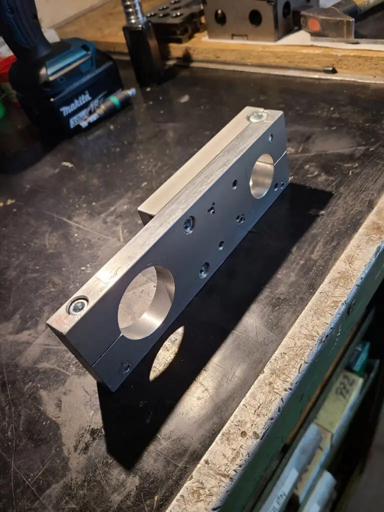
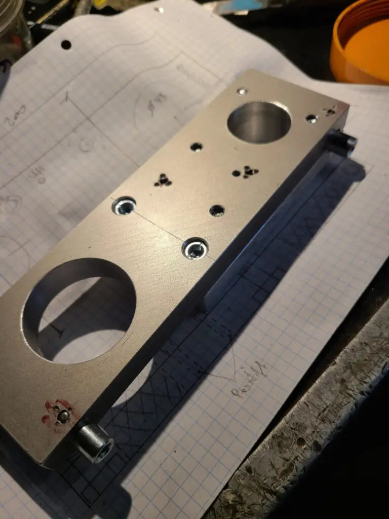
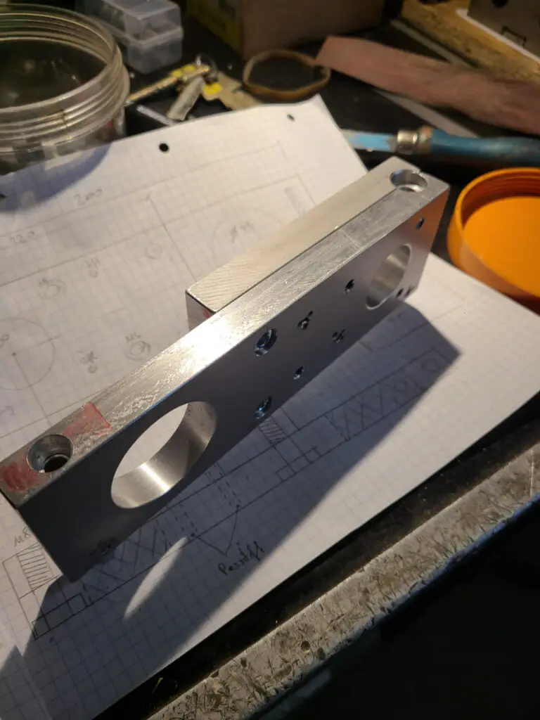
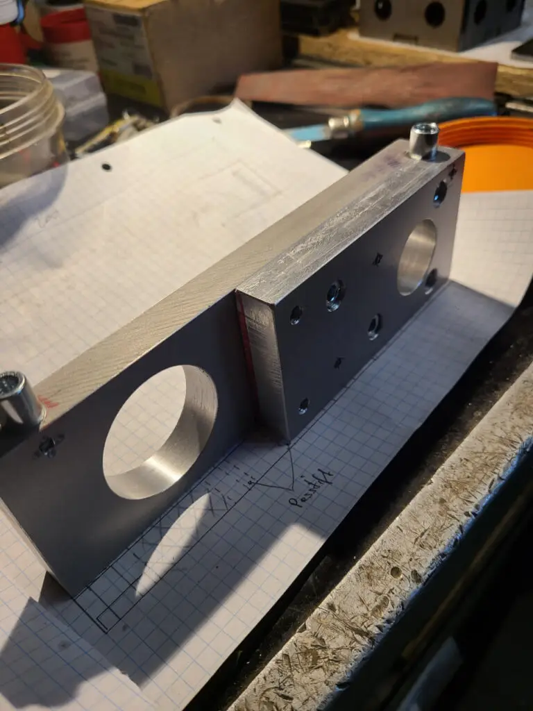




Looking Back
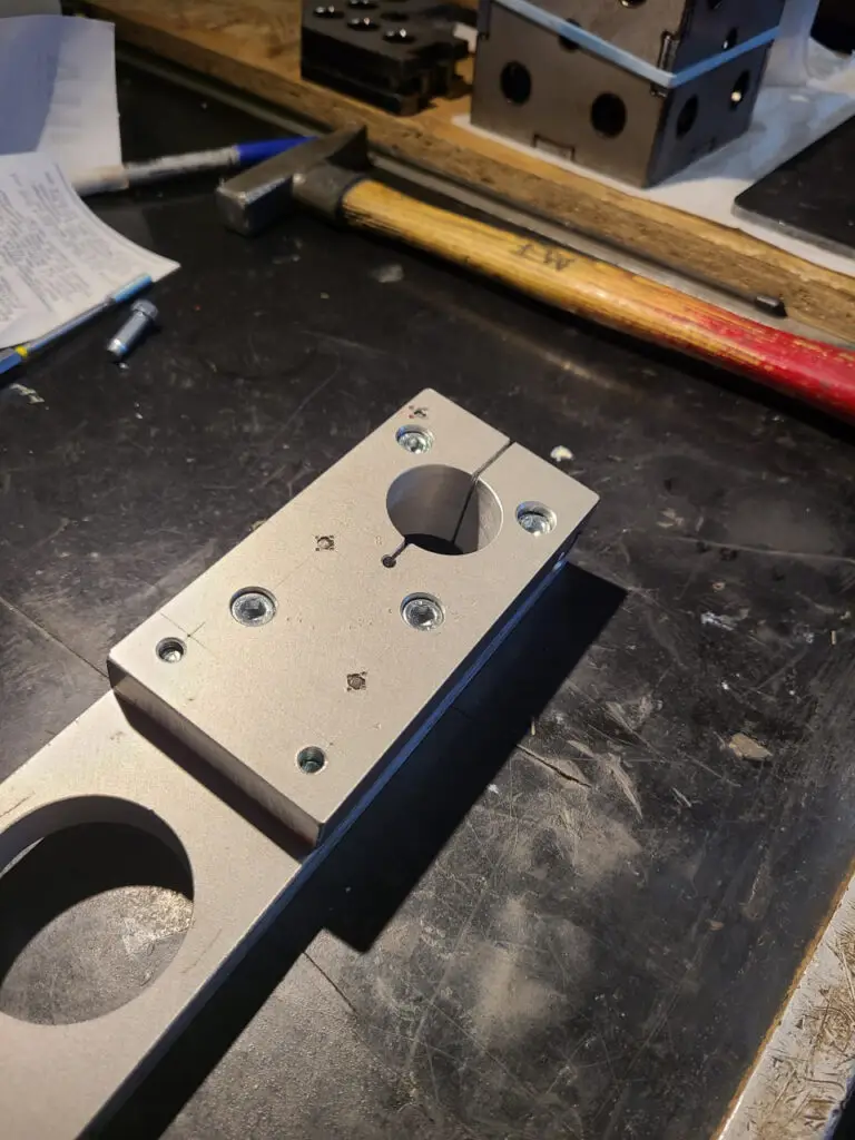
At first glance, the holder is just a bolted-together aluminum plate with two large holes. On second glance, pretty much the same.
The actual work is hidden in the details that are hardly visible on the finished part:
- A previously built holder first had to make the manufacturing process possible.
- Several plates were aligned, bolted together, and dowel-pinned.
- The large bores were made with a boring head on the drill stand.
- The MT2 taper had to be secured additionally because of the lateral forces.
- Replaceable steel threads were integrated into the aluminum construction.
- The clamping slots were made with a saw.
- A suggestion from the forum discussion led to an extended relief slot.
- And thanks to its 43 mm Euro collar, the mount originally made for a Fein BOP 6 now carries a DUSS B13.
The project shows rather well how my collection of machines gradually grew at the time.
Not only through additional machines.
But also through fixtures that allowed the existing machines to do just a little more than before.
This article documents my specific setup and the solution I made with the equipment available at the time. The improvised Morse-taper retention method described here is not a general recommendation. Rotating tools, boring heads, and inadequately secured toolholders can cause serious hazards.
How Would You Build the Holder Today?
The existing 43 mm Euro-collar holder has worked for years. If I built another one, I would mainly lengthen the quill mount and make the transition to the drill more rigid.
Have you built a similar adapter for a drill stand, or do you have experience with multi-part aluminum holders, replaceable bushings, or more rigid cantilevered designs?
I am especially interested in solutions that can still be made with a reasonably modest collection of machines. Well-reasoned criticism of my design is also expressly welcome in the comments.
Leave a Reply