

Table of Contents
I just wanted a carriage stop for the Emcomat 8.6.
Finding a suitable ready-made stop turned out to be largely unsuccessful.
Someone eventually reminded me that I already owned essentially all the tools needed to build one myself.
At least in theory.
So, pick up the workshop files and get going.
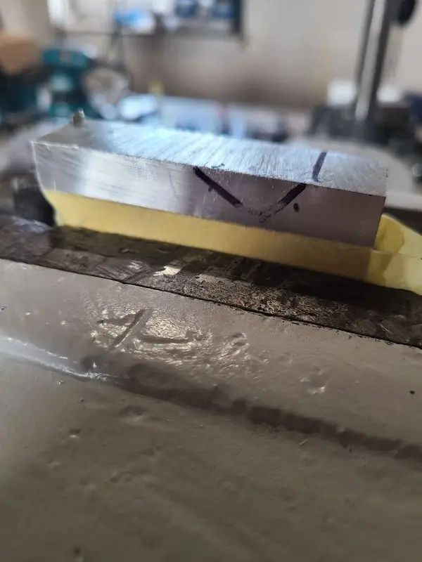
The starting point was a piece of aluminum, a roughly marked outline, and my by now much-appreciated ZAG-150 vise.
Why build a carriage stop at all?
A carriage stop on the machine bed makes it possible to bring the carriage back to the same position repeatedly.
That is useful for, among other things:
- repeated lengths
- multiple similar workpieces
- grooves and shoulders
- drilling and milling setups
- or simply as a repeatable reference for unusual setups
The stop needed to be movable and clamp reliably to the Emcomat bed.
A complicated fine adjustment was not the main goal, at least not initially.
What I mainly needed was a rigid stop that I could mount wherever I needed it.
The first blank was made the traditional way
The starting material was a leftover piece of aluminum plate.
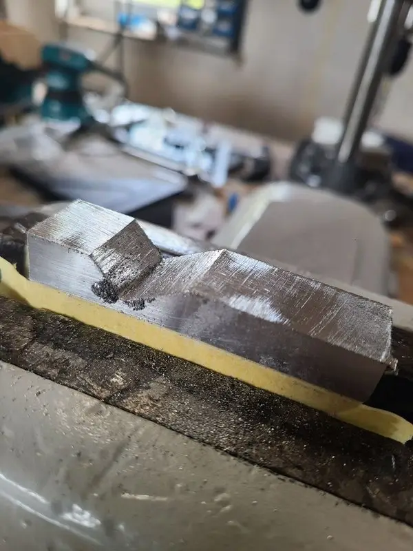
The outer shape was roughly marked out, cut free, and then worked to shape with workshop files.
Klein Kunibert, my ZAG-150 parallel vise, once again proved very useful.
The process began as classic handwork:
- mark out
- file
- check
- and discover once again that material still has to come off somewhere else
It works. It just takes longer than you convince yourself it will while marking out the shape.
Want some machine assistance?
At some point, the usual thought appeared:
Surely there must be some way to do this by machine.
I still did not have a milling machine.
But nobody had explicitly said that a lathe could not briefly help out as a shaper.
Although really calling it “shaping” was perhaps a little optimistic given the time the machining took.
It was more of a slow-shaping exercise.
The slow-shaper lathe.
A first shaping tool made from silver steel rod
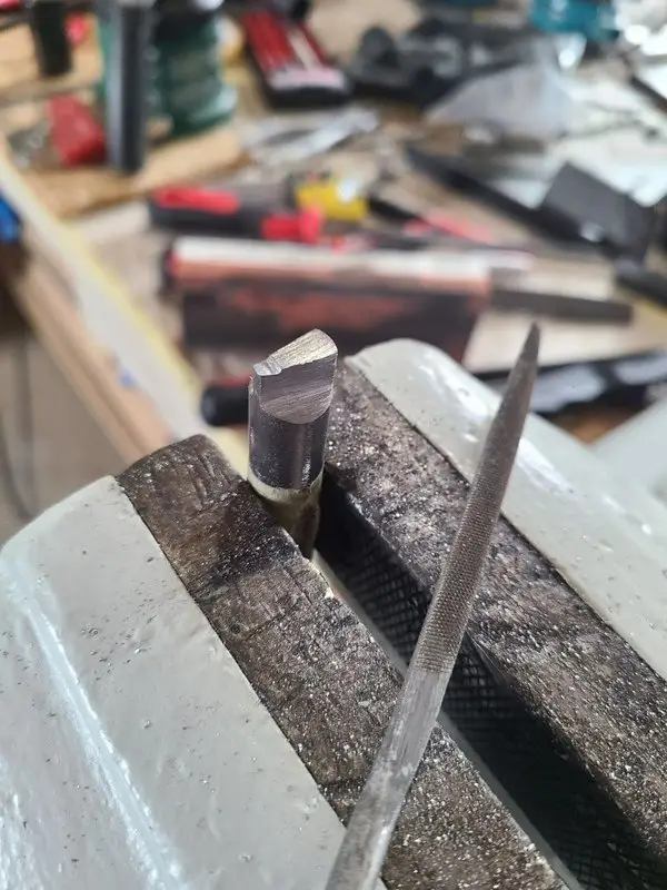
For the first attempt, I made a small shaping tool from a silver steel rod.
The material was:
- cut to length
- shaped with a file
- heated with a torch
- hardened in oil
- tempered
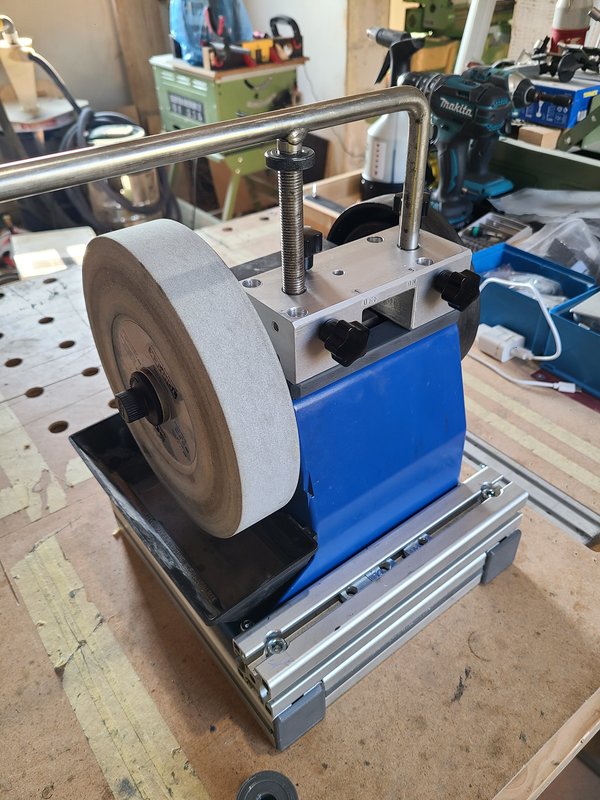
- ground on the Tormek
- and then honed on a stone
The tool worked in principle.
The cutting edge removed material, and the Emcomat really could be used as a hand-operated shaper.
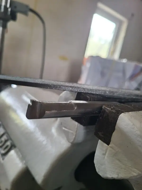
The setup did not provide enough clearance, however.
The cutting geometry and holder had not yet been thought through completely.
The tool could cut. It still was not especially practical.
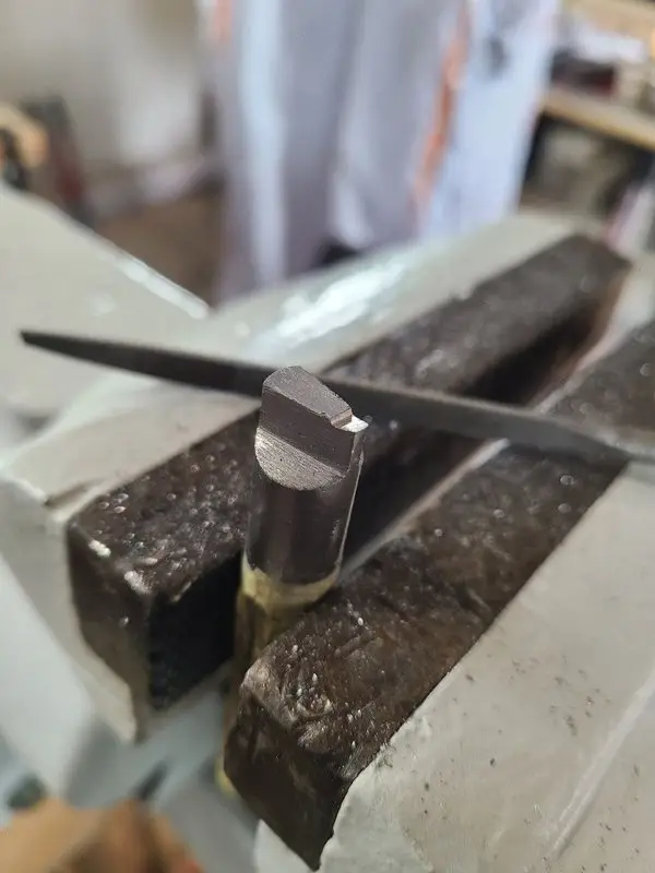
Caption: The first shaping tool worked in principle, but it had too little clearance and produced unnecessarily high cutting forces.

Caption: The close-up made it fairly obvious why this first tool worked, but was not particularly pleasant to use.
T-nuts instead of strap clamps
The T-nuts I had made earlier were extremely useful for the setup.
There was hardly enough room for conventional strap clamps and step blocks in the available setup.
The T-nuts made it possible to fasten everything compactly directly to the slide.

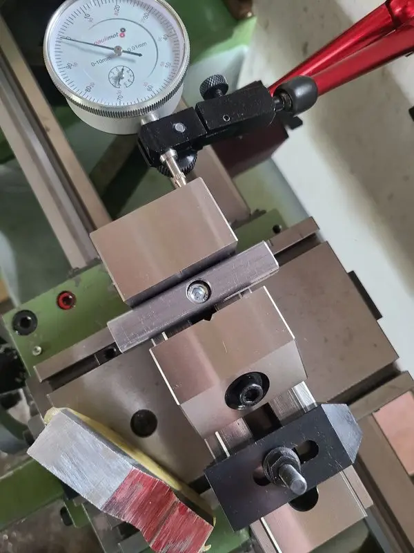
With work like this, that is often the real difference between a theoretically possible setup and one that is actually usable.
The tool is one thing. Getting it sensibly in front of the workpiece is another.
Plan B: an old 4 mm drill
After the first attempt, I changed the setup.
The plan was to drill and ream a hole in the tool holder, clamp the shank of an old broken 4 mm drill in it, and secure it with a set screw.
The drill was reground accordingly and was intended to work as a narrow shaping tool.
The idea was good. The route to it was less so.
An M5 tap stayed in the part
I had drilled only 4 mm for the set-screw thread.
That was too small for an M5 thread.
The new tap broke exactly at the exit of the hole.
That left a piece of hardened tap stuck in the tool holder.
My next plan was to extract the remains with a carbide drill.
Afterward, I had:
- a broken tap still stuck in the part
- and one fewer carbide drill
At that point, the project took a short thinking break.
So my father and I supplied the machinery with some barley electrolyte.
The second tool holder was the better solution
After the pause, I made a new holder for the reground 4 mm drill.
This version was:
- narrower
- sharper
- more accessible
- and required less cutting force
It worked much better than the first drill-rod tool.
Even the initially rough-shaped surface of the aluminum part already looked surprisingly usable.
The narrower tool was not merely a replacement after the failed thread. It was the better solution.
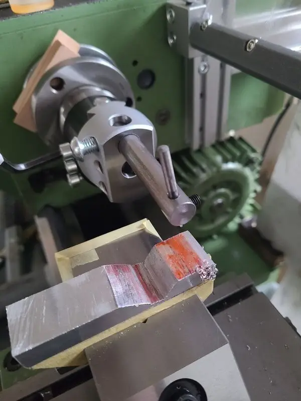
The second holder used a reground 4 mm drill as the shaping tool. It was narrower and produced noticeably lower cutting forces.
The small reground drill was unspectacular, but it worked better than the much larger first tool.
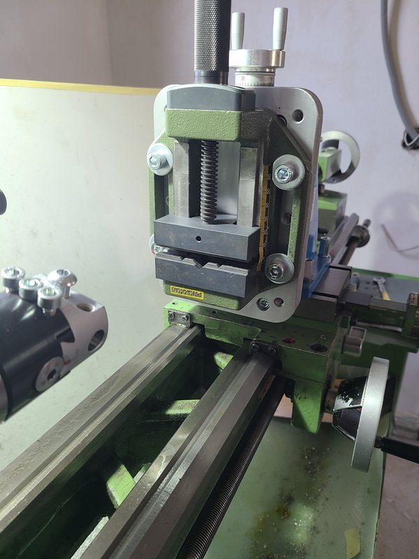
The shaping setup on the Emcomat
The final setup consisted mainly of:
- a boring head in the spindle
- the small shaping tool mounted in it
- a vise mounted on the slide
- and the lathe’s hand-operated longitudinal motion
The boring head provided a simple way to adjust the tool height.
The small reground drill was clamped in a round holder.
In this setup, the vise replaced the compound slide.
The spindle was not switched on.
The tool remained stationary. The cutting motion came entirely from cranking the carriage.
Depth was increased a tenth at a time, and the carriage was moved through the cut by hand.
I spent an entire day at the lathe without even switching it on once.
That is probably not the most economical use of a lathe. But it was a way to produce the required shape with the equipment I had.

Caption: The boring head was used to adjust the tool height. The cutting motion came entirely from cranking the carriage.
The setup was not especially elegant. But it worked—slowly, controllably, and surprisingly well.
Videos of the setup
The shaping setup can be seen in two short videos:
The wide shot in particular makes it clear why “slow shaping” is the more accurate description.
The lower clamping jaw
In addition to the aluminum body, the stop needed a separate clamping jaw for fastening it to the machine bed.
The lower part was made from a leftover piece of 22 mm hex stock.
This part was also shaped on the Emcomat.
I then aligned the aluminum body and clamping jaw with each other and clamped the two parts together.
This meant the subsequent machining operations could be referenced directly to both parts.
Pockets and through-hole on the drill stand
Pockets on both sides and a through-hole were needed to connect the two parts.
This work was done with an end mill used as a drill in the drill-press stand.
The setup was sufficient to produce the required clearances.
After machining, the two parts fit together, and the clamping action worked very well during the first trial fit.
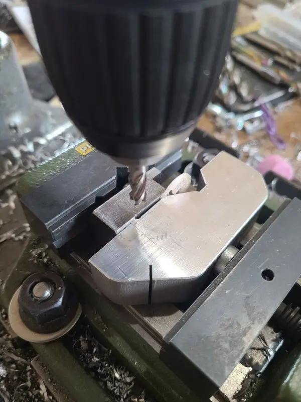
Caption: The pockets and through-hole were made with an end mill in the drill stand. Not ideal, but sufficient for this purpose.
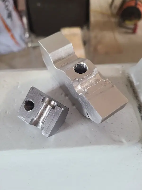
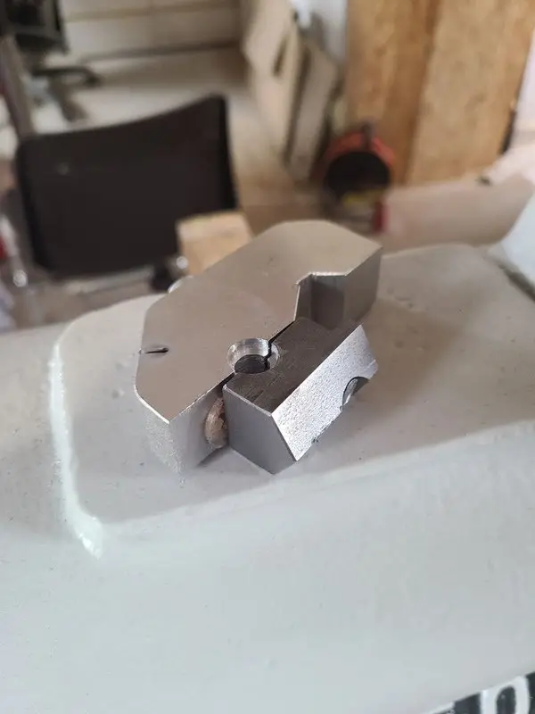
After the pockets were machined, the main body and clamping jaw fit together cleanly.
A small guide pin keeps the clamping jaw in position
A small turned guide pin—or spool—sits between the main body and the clamping jaw.
This part serves several purposes:
- The clamping jaw remains movable along this axis.
- Its position is guided.
- It cannot twist freely while being tightened.
- The spool cannot work its way out sideways.
At first glance, the shape looks more elaborate than a simple pin with a retaining ring.
In the assembled mechanism, however, it allows the loose clamping jaw to move in a controlled way without needing to be rearranged every time it is fitted.

The small shaft was more than just a pin. It guided the clamping jaw and kept the entire mechanism from twisting.
A ballpoint-pen spring had to help
A small compression spring was added as well.
It came from a workshop ballpoint pen, which involuntarily sacrificed to the project.
The spring pushes the clamp apart when loosened and makes the stop easier to move or remove.
A slightly stronger spring might be more convenient.
The existing solution was sufficient for the initial testing, however.
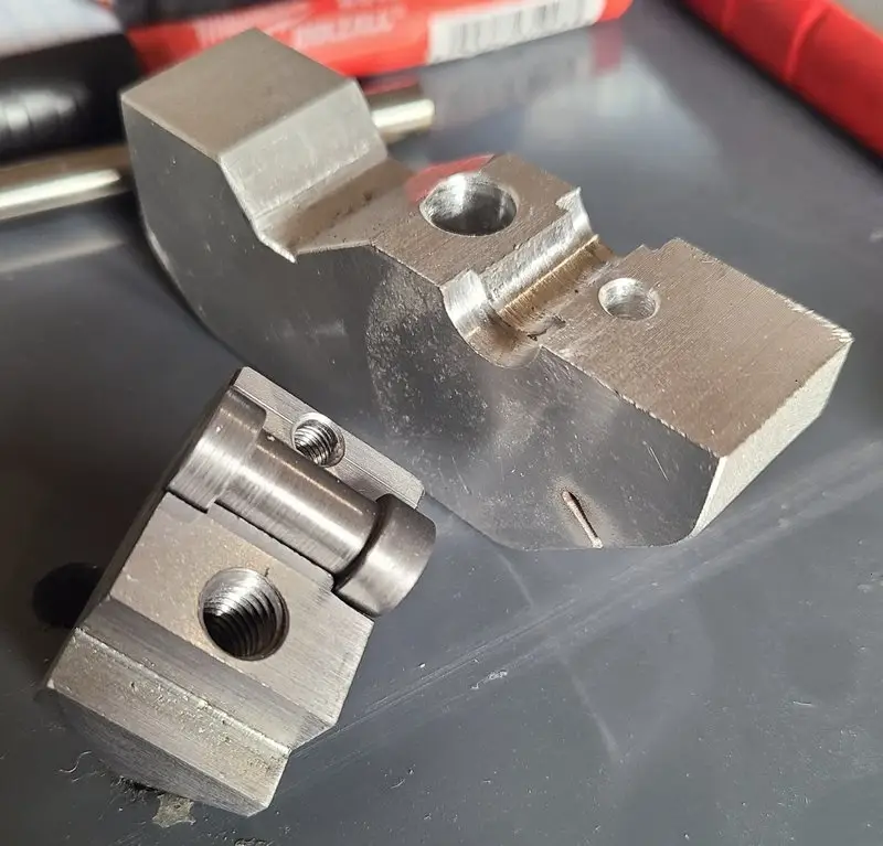
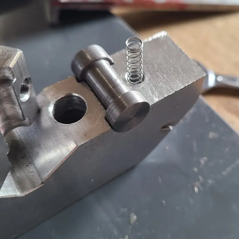
Caption: The small turned guide pin guides the clamping jaw and prevents it from twisting. A ballpoint-pen spring opens the clamp when it is loosened.

Caption: In the nearly finished assembly, it became clear how simple the mechanism actually is—provided you ignore the route that led there.
M8 instead of an additional clamping lever
A dedicated clamping lever was not planned.
The clamping action is provided by an M8 screw with a 6 mm hex socket.
The matching hex key is already kept by the Emcomat for several other M6 and M8 screws.
An additional lever would have taken up space, projected into the work area, and possibly created just another collision point or a place for long chips to collect.
The screw is less spectacular. But it does the job.
Access should have been from below
Shortly before completion, I realized that the screw would probably be easier to access from below.
In the version I built, the screw head is on top and therefore closer to the chip area.
A clamp operated from below would have several advantages:
- no screw head on the top surface
- less surface for chips to catch on
- a clearer work area
- and a visually cleaner top surface
Naturally, this realization came only when almost everything was finished.
What worked
At the documented stage, the following worked:
- the clamping action on the machine bed
- moving and positioning the stop
- guiding the lower clamping jaw
- operation using the M8 screw
- and the generally rigid construction
The clamping action was especially satisfying.
The stop could be fastened reliably to the bed even though the individual machining steps had been carried out with very simple equipment.

Caption: In the end, the stop sat where it was supposed to. The clamping worked, and its position on the bed could be checked cleanly.
The first practical trial fit was pleasantly uneventful—which is usually a good sign with a part like this.
What did not work
Not every step was successful.
The failed or discarded attempts included:
- the first shaping tool with insufficient relief
- the first tool holder
- the M5 thread with a tap-drill hole that was too small
- the attempt to remove the broken tap with a carbide drill
- and the rather late realization that the clamping screw sits directly in the chip area
These detours are part of the project.
What I would do differently today
Provide access to the clamping screw from below
Access from below would probably be the cleaner solution.
The top surface would remain clear, and the screw would be less exposed to flying chips. A fixed handle or lever would then be simple and straightforward.
Start with a smaller shaping tool
The first drill-rod tool was unnecessarily wide and required too much clearance.
The reground 4 mm drill used later produced lower cutting forces and worked better.
Drill the correct tap hole
A 4 mm hole was too small for the intended M5 thread.
That realization cost me a new tap and then the only carbide drill I had on hand.
Think through the clamping mechanism earlier
The guide pin, spring, clamping jaw, and screw access partly developed only during fabrication.
If I made a second stop, I would define the entire clamping movement more precisely before the first saw cut.
Then again, that would almost count as planning.
Looking back
A carriage stop is not a particularly large part.
With a milling machine, making it probably would not have been especially remarkable either.
I did not have one.
So instead:
- the basic shape was filed
- a custom shaping tool was hardened and ground
- the first tool setup was discarded again
- a tap was broken
- a carbide drill was sacrificed
- an old 4 mm drill was reground into a shaping tool
- the Emcomat was cranked by hand for a full day without the spindle running
- a clamping jaw was made from leftover 22 mm hex stock
- and the drill stand was once again declared to be a milling machine
In the end, a working carriage stop still emerged.
Not by the shortest route, but by one that at least left something worth telling—and ended with a working stop.
Image gallery


Forum discussion (German)
The build was documented and discussed in the forum.
The original photos, both videos, and additional notes on the unusual shaping setup can also be found there:
Forum discussion: Bed and carriage stop for the Emcomat 8.6
How would you have solved it?
If you have built a bed stop yourself—or had to repurpose a lathe because no milling machine was available—I would be interested in your experience.
I would be particularly interested in solutions for:
- compact clamping mechanisms on the machine bed
- better access to the clamping screw
- narrow shaping tools for improvised setups
- or generally better ideas for producing shapes like these without a milling machine
Notes on what does—or does not—hold up in long-term use with a stop like this are also very welcome.
This article documents my specific setup and the improvised machining methods used for it. A rigid stop must never be approached blindly under powered feed. Workholding, tool geometry, cutting forces, and possible collisions must be assessed independently for the specific machine setup.
Leave a Reply